5 Configuration
D-Link Web Smart Switch User Manual
44
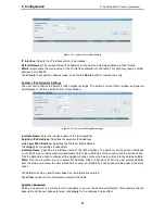
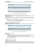
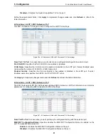
port is forced to half-duplex operation) the p2p status changes to operate as if the p2p value were
False
. The
default setting for this parameter is
Auto
.
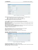
Restricted Role:
Toggle between
True
and
False
to set the restricted role state of the packet. If set to
True
,
the port will never be selected to be the Root port. The default value is
False
.
Restricted TCN:
Toggle between
True
and
False
to set the restricted TCN of the packet. Topology Change
Notification (TCN) is a BPDU that a bridge sends out to its root port to signal a topology change. If set to
True
, it stops the port from propagating received TCN and to other ports. The default value is
False
.
Click
Apply
for the settings to take effect. Click
Refresh
to renew the page.
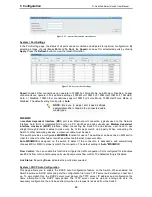
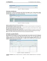
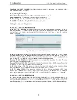
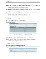
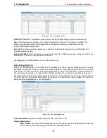
L2 Functions > Link Aggregation > Port Trunking
The Trunking function enables the combining of two or more ports together to increase bandwidth. Up to
eight Trunk groups may be created, and each group consists up to eight ports. Select the ports to be
grouped together, and then click
Apply
to activate the selected Trunking groups. Two types of link
aggregation can be selected:
Static -
Static link aggregation.
LACP -
LACP (Link Aggregation Control Protocol) is enabled on the device. LACP allows for the
automatic detection of links in a Port Trunking Group.
Disable -
Remove all members in this trunk group.
Figure 5.45 – L2 Functions > Link Aggregation > Port Trunking
NOTE:
Each combined trunk port must be
connected to devices within the same VLAN
group.
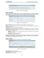
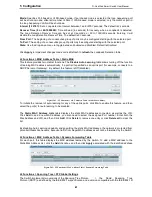
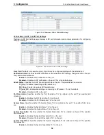
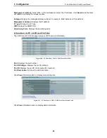
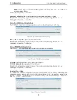
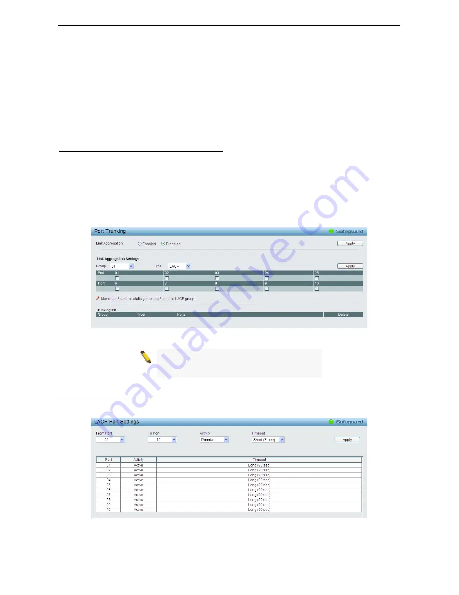
L2 Functions > Link Aggregation > LACP Port Settings
The LACP Port Settings is used to create port trunking groups on the Switch. The user may set which ports
will be active and passive in processing and sending LACP control frames.
Figure 5.46 – L2 Functions > Link Aggregation > LACP Port Settings
From Port:
The beginning of a consecutive group of ports may be configured starting with the selected port.
Summary of Contents for DGS-1210-10P
Page 1: ......
Page 32: ...5 Configuration D Link Web Smart Switch User Manual 2 27 7 Figure 5 16 User Guide Micro Site...
Page 109: ......

