5 Configuration
D-Link Web Smart Switch User Manual
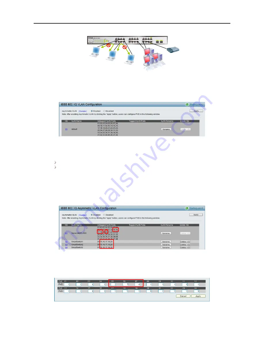
Figure 50 – Configuration > 802.1Q VLAN > Asymmetric VLAN Example
1.
Enable Asymmetric VLAN
Enable Asymmetric VLAN and click
Apply
button. The overlapping VLAN cannot be configured
unless this function is enabled..
Figure 51 – Configuration > 802.1Q VLAN > Asymmetric VLAN - Enabling Asymmetric VLAN
2.
Configure the shared VLAN (VLAN 1) and access VLANs (VLAN 2, 3, 4)
In this case, default VLAN is used as shared VLAN, and ports that shared in the network are:
Ports 15-18 are connected to the server
Port 20 is connected to the firewall
The group of shared ports needs to be included for all the VLANs. In this case, port 15-18, 20 are
already belong to VLAN 1, therefore no changes is needed.
VLAN 2 is then configured to include ports 15-18, 20 (shared VLAN ports) and the set of ports to be
separated from the other subset VLANs (For example, port 5). VLAN 3 and 4 are then configured to
include shared ports and the set of ports to be separated from the other subset VLANs (For example,
port 6 and 7). Therefore we have three VLANs that share ports and are separated from each other so
cannot communicate with each other.
Figure 52 – Configuration > 802.1Q VLAN > Asymmetric VLAN – Create VLANs
3.
Configuring the PVID of access VLAN
Configure the PVID setting located in the bottom of VLAN configuration page. The user needs to set
the shared set of ports as PVID 1, the other separated groups of ports as PVID 2, 3 and 4.
Figure 53 – Configuration > 802.1Q VLAN > Asymmetric VLAN – Assign PVID
After configuration, the user is able to share the network resources set on the shared group of ports
(nominated as PVID 1), with both smaller subsets of VLANs (nominated PVID 2, 3 and 4). However, VLAN 2,
PC 2 (Port 6)
PC 3 (Port 7)
Firewall
PC 1 (Port 5)
Servers
3
3
0
0


