8
u
EN
G
LI
S
H
Installing Boards on the DGS-6600 Series
Chassis Switch
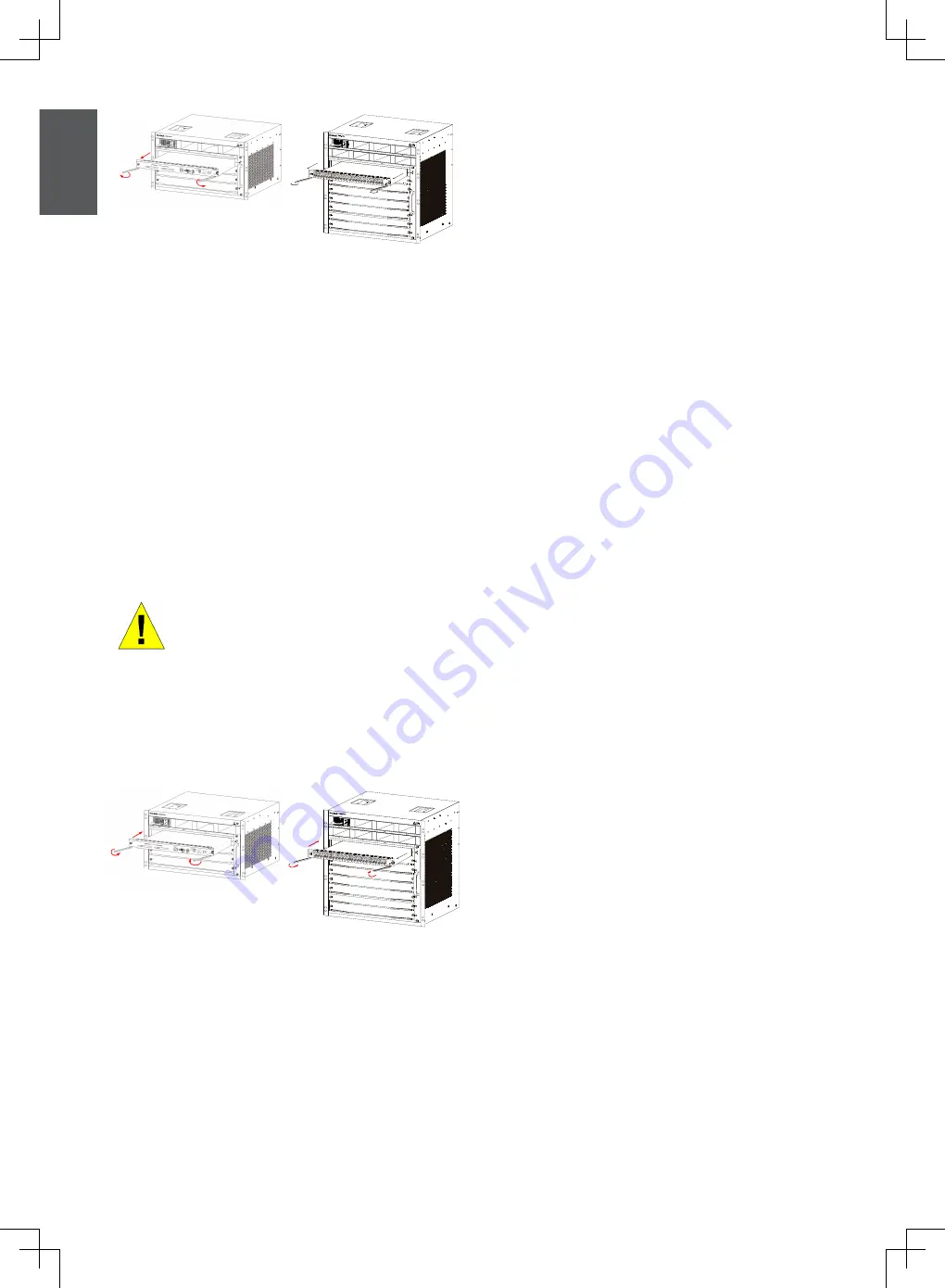
Carry out the following steps to install boards in the
DGS-6600 Series Chassis Switch:
1.
Remove the component card or blank panel as
instructed in the section.
2. Insert the new board into the guide rail of the
vacant slot.
3.
Use the levers on the left and right hand side
to push the board into position and tighten
the two captive screws on the board using a
straight screw driver.
Figure 11. Removing a board from the chassis
Caution
1. Take care not to hold the edge
of the PCB or collide the compo-
nents of the PCB.
2. Always use the levers to plug/
unplug a PCB module. Never
use force to remove a PCB
module.
6
7
8
Figure 12. Installation Check
Installation Check
Verify that the external AC power supply provides
the correct voltage and frequency.
Verify that the cabinet has been fastened
completely, and does not move or tilt.
Verify that the Power Supplies, CM and Line
Cards have been installed in the chassis.
6
7
8
Verify that the optical fiber and twisted pair cables
match their respective interfaces.
Verify that the cables have been bound
appropriately and are not subject to any excess
stress.
Verify that the power cables are in good condition
and comply with safety requirements.
Verify that the power module has been firmly
installed into the backplane connector.
Turn on the power switch and verify that the
power module is operating correctly.
Unpacking Inspection
Requirements
Checklist
1.
DGS-6604 Chassis Carton
DGS-6604 Chassis (no cards installed)
2. Card Module Carton (s)
•
1 CM Card (DGS-6600-CM or DGS-6600-CM-II)
•
Line Cards (specific per order)
•
Power Supplies Units (number specific per
order)
3. DGS-6600 Series Switch Accessories Carton
including:
• AC Power Cord
•
RS-232 Console Cable (9 pin D-Sub)
•
USB Console Cable (Type A to Type B)
• Fan Tray
• Air Filter
• CD software and manual
• QIG


