background image

DIS-200G Series Industrial Gigabit Ethernet Smart Managed Switch 

44 


Click the 

Back

 button to return to the previous window. 


RMON Alarm Settings 

This window is used to configure and display alarm entries to monitor an interface. 
To view the following window, click 

Management > RMON > RMON Alarm Settings

, as shown below: 


The fields that can be configured are described below: 

Parameter   

Description   

Index 

Enter the alarm index. The range is from 1 to 65535. 

Interval 

Enter the interval in seconds for the sampling of the variable and 

checking against the threshold. The valid range is from 1 to 

2147483647 seconds. 

Variable 

Enter the object identifier of the variable to be sampled. 

Type 

Select the monitoring type. Options to choose from are 

Absolute


and 

Delta

Rising Threshold 

Enter the rising threshold value between 0 and 2147483647. 

Falling Threshold 

Enter the falling threshold value between 0 and 2147483647. 

Rising Event Number 

Enter the index of the event entry that is used to notify the rising 

threshold crossing event. The valid range is from 1 to 65535. If not 

specified, no action is taken while crossing the ringing threshold. 

Falling Event Number 

Enter the index of the event entry that is used to notify the falling 

threshold crossing event. The valid range is from 1 to 65535. If not 

specified, no action is taken while crossing the falling threshold. 

Owner 

Enter the owner string up to 127 characters. 

Click the 

Add

 button to add a new entry based on the information entered.   

Click the 

Delete

 button to remove the specified entry. 

Enter a page number and click the 

Go

 button to navigate to a specific page when multiple pages exist. 

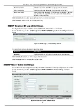
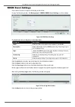
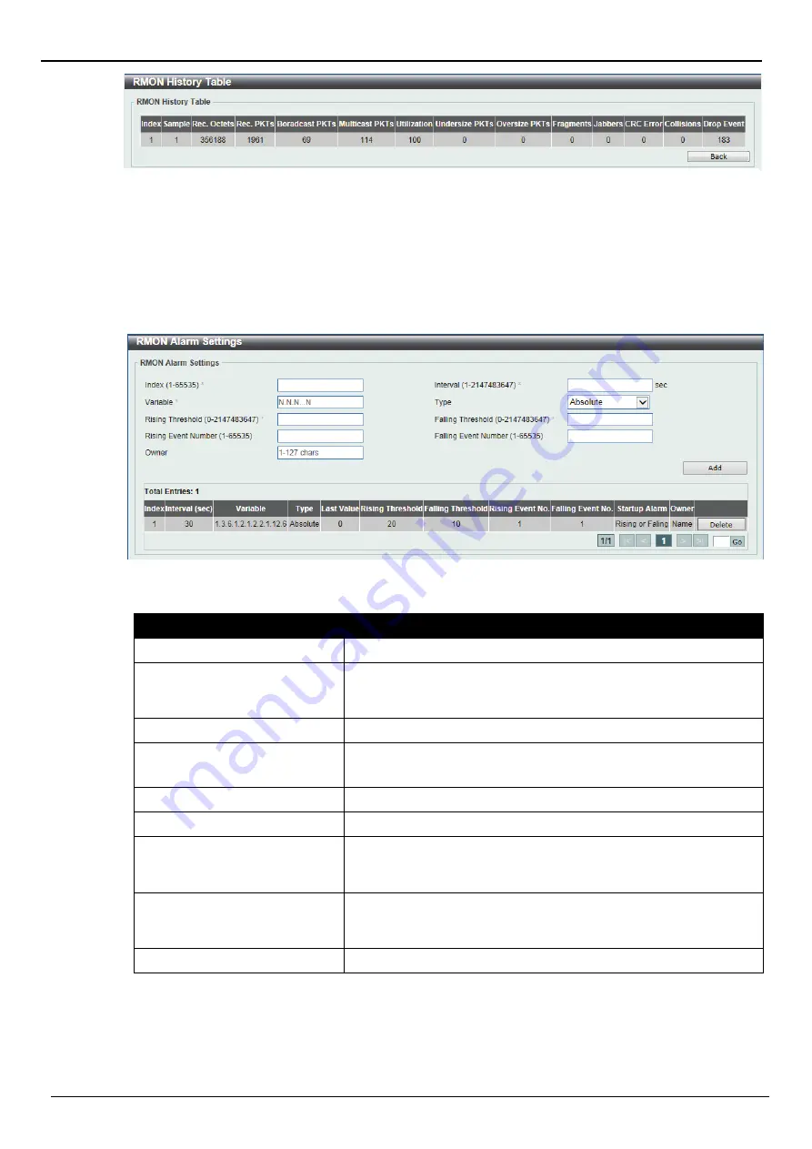
Figure 5-14 RMON History Table window 

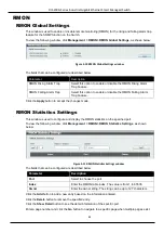
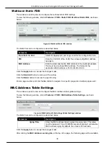
Figure 5-15 RMON Alarm Settings window 

Summary of Contents for Dis-200G Series

Page 1: ...DIS 200G Series Industrial Gigabit Ethernet Smart Managed Switch...

Page 2: ...d in this text D Link and the D Link logo are trademarks of the D Link Corporation Microsoft and Windows are registered trademarks of the Microsoft Corporation Other trademarks and trade names may be...

Page 3: ...illance Mode 10 3 SAVE AND TOOLS 11 SAVE CONFIGURATION 11 FIRMWARE INFORMATION 11 FIRMWARE UPGRADE BACKUP 12 Firmware Upgrade from HTTP 12 Firmware Upgrade from TFTP 12 Firmware Backup to HTTP 13 Firm...

Page 4: ...ings 28 Time Zone Settings 29 SNTP SETTINGS 30 TIME PROFILE 31 5 MANAGEMENT 32 USER ACCOUNT SETTINGS 32 PASSWORD ENCRYPTION 33 SNMP 34 SNMP Global Settings 35 SNMP View Table Settings 36 SNMP Communit...

Page 5: ...figuration Identification 71 STP Instance 72 MSTP Port Information 72 ERPS G 8032 73 ERPS 73 ERPS Profile 75 LOOPBACK DETECTION 77 LINK AGGREGATION 78 L2 MULTICAST CONTROL 81 IGMP Snooping 81 MLD Snoo...

Page 6: ...ROL 100 Web Authentication 101 WAC Port Settings 102 WAC Customize Page 103 9 OAM 104 CABLE DIAGNOSTICS 104 DDM 105 DDM Settings 105 DDM Temperature Threshold Settings 106 DDM Voltage Threshold Settin...

Page 7: ...ON 122 POE SCHEDULING 123 TIME 125 Clock Settings 125 SNTP Settings 125 SURVEILLANCE SETTINGS 126 SURVEILLANCE LOG 128 HEALTH DIAGNOSTIC 129 TOOLBAR 130 Wizard 130 Tools 130 Save 133 Help 134 Online H...

Page 8: ...inciples for Local Area Networks Other Documentation The documents below are a further source of information in regards to configuring and troubleshooting the switch All the documents are available ei...

Page 9: ...ent you should pay special attention to these indicators Each example below provides an explanatory remark regarding each type of indicator NOTE A note indicates important information that helps you m...

Page 10: ...requests with MIB objects stored in the database The SNMP agent updates the MIB objects to generate statistics and counters Web based Management Interface After successfully installing the Switch the...

Page 11: ...Password in the corresponding fields and click Login The default username is admin and the default password is admin This will open the Web based user interface The Switch s management features availa...

Page 12: ...b mode specifically designed to assist the user with surveillance features supported by the Switch NOTE The Web Mode can only be changed when one user session is connected to the Web UI of the Switch...

Page 13: ...nce Mode Web UI automatically The fields that can be configured are described below Parameter Description Static Select this option to manually configure and use IP address settings on this switch DHC...

Page 14: ...word for the user account here Confirm Password Enter the new password again for confirmation here Tick the Ignore the wizard next time option to skip the Smart Wizard on the next login Click the Exit...

Page 15: ...the SNMP function Select the Disabled option to disable the SNMP function Tick the Ignore the wizard next time option to skip the Smart Wizard on the next login Click the Exit button to discard the ch...

Page 16: ...pen folders and click the hyperlinked window buttons and subfolders contained within them to display windows AREA 2 Presents Switch status based on user selection and the entry of configuration data I...

Page 17: ...ders contained within them to display windows AREA 2 In this area configuration and monitoring window frames are available based on the selections made in area 1 AREA 3 Presents a toolbar used to acce...

Page 18: ...he file system of the Switch This is to prevent the loss of configuration in the event of a power failure To view the following window click Save Save Configuration as shown below Click the Apply butt...

Page 19: ...lick the Upgrade button to initiate the firmware upgrade Firmware Upgrade from TFTP This window is used to initiate a firmware upgrade from a TFTP server To view the following window click Tools Firmw...

Page 20: ...e a firmware backup to a TFTP server To view the following window click Tools Firmware Upgrade Backup Firmware Backup to TFTP as shown below The fields that can be configured are described below Param...

Page 21: ...and overwrite the start up configuration file on the Switch Click the Restore button to initiate the configuration restore Configuration Restore from TFTP This window is used to initiate a configurat...

Page 22: ...from the Switch Exclude Username Password Specify this radio button to back up the running configuration file exclude username password from the Switch Click the Backup button to initiate the configu...

Page 23: ...to initiate a system log backup to a TFTP server To view the following window click Tools Log Backup Log Backup to TFTP as shown below TThe fields that can be configured are described below Parameter...

Page 24: ...imes desired to attempt to Ping the IPv4 address configured in this window Users may enter a number of times between 1 and 255 Tick the Infinite check box to keep sending ICMP Echo packets to the spec...

Page 25: ...ude the IP address from being changed Select the The Switch will be reset to its factory defaults including IP address option to reset the Switch s configuration to its factory default settings Click...

Page 26: ...tem Name System Location and System Contact to aid in defining the Switch To view the following window click System System Information Settings as shown below The fields that can be configured are des...

Page 27: ...lected users can enter the IPv4 address of this interface manually in the fields provided When the DHCP option is selected this interface will obtain IPv4 information automatically from the DHCP serve...

Page 28: ...n state is enabled IPv6 link local address will assigned to management VLAN automatically If state is disabled and static IPv6 address is not set the IPv6 feature will be disabled on switch Static IPv...

Page 29: ...rough a cross over cable Cross Select this option for cross cabling If this option is selected the port is in the MDI mode and can be connected to a port in the MDIX mode on another switch through a s...

Page 30: ...e size of up to 9600 bytes To view the following window click System Port Configuration Jumbo Frame as shown below The fields that can be configured are described below Parameter Description From Port...

Page 31: ...circuit protection automatically disables the port if there is a short Other ports will remain active Based on 802 3af at PDs receive power according to the following classification PSE provides power...

Page 32: ...ew the following window click System PoE PoE Configuration as shown below The fields that can be configured are described below Parameter Description From Port To Port Select the appropriate port rang...

Page 33: ...nction on the specified port s PD IP Address Enter the IP address of the PD here Poll Interval Enter the poll interval here This is the interval between ping messages from the system to PDs connected...

Page 34: ...escribed below Parameter Description Buffer Log State Select whether the enable or disable the buffer log s global state Click the Apply button to accept the changes made System Log Server Settings Th...

Page 35: ...ge when multiple pages exist Time and SNTP The Simple Network Time Protocol SNTP is a protocol for synchronizing computer clocks through the Internet It provides comprehensive mechanisms to access nat...

Page 36: ...tting and Date Setting Disabled Select to disable the summer time setting Recurring Setting Select to configure the summer time that should start and end on the specified week day of the specified mon...

Page 37: ...f the month that summer time will start From Month Select the month that summer time will start From Year Enter the year that the summer time will start From Time HH MM Select the time of the day that...

Page 38: ...ing window click System Time Profile as shown below The fields that can be configured are described below Parameter Description Range Name Enter the name of the time range This name can be up to 32 ch...

Page 39: ...his administrator user account level can monitor all system information and change any of the system configuration settings expressed in this guide To view the following window click Management User A...

Page 40: ...iew the following window click Management Password Encryption as shown below The fields that can be configured are described below Parameter Description Password Encryption State Choose the enable or...

Page 41: ...s The first part is to maintain a list of users and their attributes that are allowed to act as SNMP managers The second part describes what each user on that list can do as an SNMP manager The Switch...

Page 42: ...obal Settings as shown below The fields that can be configured for SNMP Global Settings are described below Parameter Description SNMP Global State Select this option to enable or disable the SNMP fea...

Page 43: ...Settings as shown below The fields that can be configured are described below Parameter Description View Name Type an alphanumeric string of up to 32 characters This is used to identify the new SNMP v...

Page 44: ...s used to identify members of an SNMP community This string is used like a password to give remote SNMP managers access to MIB objects in the Switch s SNMP agent View Name Enter an alphanumeric string...

Page 45: ...Pv2c and SNMPv3 SNMPv1 Select to allow the group user to use the SNMPv1 security model SNMPv2c Select to allow the group user to use the SNMPv2c security model SNMPv3 Select to allow the group user to...

Page 46: ...Engine ID is a unique identifier used for SNMP V3 implementations on the Switch To view the following window click Management SNMP SNMP Engine ID Local Settings as shown below The fields that can be...

Page 47: ...entication level This field will require the user to enter a password or a key SHA Specify that the HMAC SHA authentication protocol will be used This field will require the user to enter a password o...

Page 48: ...lable NoAuthNoPriv Specify that there will be no authorization and no encryption of packets sent between the Switch and a remote SNMP manager AuthNoPriv Specify that authorization will be required but...

Page 49: ...nges made RMON Statistics Settings This window is used to configure and display the RMON statistics on the specified port To view the following window click Management RMON RMON Statistics Settings as...

Page 50: ...35 Bucket Number Enter Specifies the number of buckets specified for the RMON collection history group of statistics The range is from 1 to 65535 The default value is 50 Interval Enter the time in sec...

Page 51: ...ng Threshold Enter the rising threshold value between 0 and 2147483647 Falling Threshold Enter the falling threshold value between 0 and 2147483647 Rising Event Number Enter the index of the event ent...

Page 52: ...pe Options to choose from are None Log Trap and Log and Trap Community Enter the community string The string can be up to 127 characters Owner Enter the owner string The string can be up to 127 charac...

Page 53: ...ick the Apply button to accept the changes made D Link Discovery Protocol This window is used to configure and display D Link Discovery Protocol DDP To view the following window click Management D Lin...

Page 54: ...bed below Parameter Description Port Allows the selection of the port number on which the MAC address entered resides VID Enter the VLAN ID on which the associated unicast MAC address resides MAC Addr...

Page 55: ...ck the Delete All button to remove all the entries Click the Delete button to remove the specific entry Enter a page number and click the Go button to navigate to a specific page when multiple pages e...

Page 56: ...disable the MAC address learning function on the ports specified here Click the Apply button to accept the changes made MAC Address Table This window is used to view the entries listed in the MAC add...

Page 57: ...LAN Configuration Wizard as shown below The fields that can be configured are described below Parameter Description Create VLAN VID Select and enter a new VLAN ID Configure VLAN VID Select and enter a...

Page 58: ...Click to allow an individual port to be specified as a non VLAN member Click the All button to select all ports Native VLAN PVID Click to designate the port as native VLAN Click the All button to sele...

Page 59: ...e Click the Delete button to remove the specific entry Click the Edit button to re configure the specific entry Enter a page number and click the Go button to navigate to a specific page when multiple...

Page 60: ...N creation function here Join Time Enter the Join Time value in centiseconds This value must be between 1 and 20 centiseconds By default this value is 20 centiseconds Leave Time Enter the Leave Time v...

Page 61: ...o accept the changes made GVRP Advertise VLAN This window is used to view and configure the GVRP advertised VLAN settings To view the following window click L2 Features VLAN GVRP GVRP Advertise VLAN a...

Page 62: ...GVRP Forbidden VLAN as shown below The fields that can be configured are described below Parameter Description From Port To Port Select the appropriate port range used for the configuration here Acti...

Page 63: ...tric VLAN function Click the Apply button to accept the changes made VLAN Interface This window is used to view and configure VLAN interface settings To view the following window click L2 Features VLA...

Page 64: ...ss Hybrid and Trunk Acceptable Frame Select the acceptable frame behavior option here Options to choose from are Tagged Only Untagged Only and Admit All Ingress Checking Select this option to enable o...

Page 65: ...gged or Tagged parameters Allowed VLAN Range Enter the allowed VLAN range information here Click the Apply button to accept the changes made Click the Back button to return to the previous window When...

Page 66: ...een 1 and 4094 Action Select the action that will be taken here Options to choose from are All Add Remove and Except Allowed VLAN Range Enter the allowed VLAN range information here Click the Apply bu...

Page 67: ...ue is 720 minutes The aging time is used to remove a port from surveillance VLAN if the port is an automatic surveillance VLAN member When the last surveillance device stops sending traffic and the MA...

Page 68: ...tion To view the following window click L2 Features VLAN Auto Surveillance VLAN MAC Settings and Surveillance Device as shown below The fields that can be configured are described below Parameter Desc...

Page 69: ...ion Click the Edit button to configure the state and description of the IP camera After click the More Detail button the following window will appear Guide After click the Edit button the following wi...

Page 70: ...ew the list of IP cameras that are connected to the NVR Click the Edit button to configure the description of the NVR Guide After click the IP Camera List button the following window will appear Click...

Page 71: ...Parameter Description Voice VLAN State Select this option to enable or disable the voice VLAN Voice VLAN ID Enter the voice VLAN ID The value is range from 2 to 4094 Voice VLAN CoS Select the priority...

Page 72: ...tion From Port To Port Select the appropriate port range used for the configuration here State Select this option to enable or disable the state of the port Mode Select the mode of the port Options to...

Page 73: ...ow Parameter Description OUI Address Enter the OUI MAC address Mask Enter the OUI MAC address matching bitmask Description Enter the description for the user defined OUI with a maximum of 32 character...

Page 74: ...and full processing of frames regardless of administrative errors in defining VLANs and their respective spanning trees Each switch utilizing the MSTP on a network will have a single MSTP configuratio...

Page 75: ...ges 802 1Q 2005 MSTP 802 1D 2004 RSTP 802 1D 1998 STP Forwarding Learning Disabled Disabled Disabled No No Discarding Discarding Blocking No No Discarding Discarding Listening No No Learning Learning...

Page 76: ...on STP Mode Select the STP mode used here Options to choose from are MSTP RSTP and STP Click the Apply button to accept the changes made The fields that can be configured for STP Traps are described b...

Page 77: ...propriate port range used for the configuration here Port Fast Select the port fast option here Options to choose from are Network Disabled and Edge In the Network mode the port will remain in the non...

Page 78: ...will show the MAC address to the device running MSTP Revision Level Enter the revision level value here This value must be between 0 and 65535 By default this value is 0 This value along with the Conf...

Page 79: ...exist MSTP Port Information This window is used to view and configure the MSTP port information settings To view the following window click L2 Features Spanning Tree MSTP Port Information as shown be...

Page 80: ...ton the following window will appear The fields that can be configured are described below Parameter Description Instance ID Select the checkbox and enter the ERP instance number here This value must...

Page 81: ...annel VLAN Select the checkbox and enter the R APS channel VLAN s ID for the ERP instance here The APS channel VLAN of a sub ring instance is also the virtual channel of the sub ring This value must b...

Page 82: ...lect the checkbox and then select the RPL port option here Options to choose from are Port0 and Port1 The option selected will be configured as the RPL port RPL Role Select the checkbox and then selec...

Page 83: ...l appear The fields that can be configured are described below Parameter Description Revertive Select the checkbox and then select the revertive state Options to choose from are Enable and Disabled Th...

Page 84: ...Loopback Detection Select to enable or disable loopback detection The default is Disabled Time Interval Enter the interval in seconds that the device will transmit all the CTP Configuration Test Prot...

Page 85: ...a multiple of a single link s bandwidth Link aggregation is most commonly used to link a bandwidth intensive network device or devices such as a server to the backbone of a network The Switch allows...

Page 86: ...are described below Parameter Description From Port To Port Select the appropriate port range used for the configuration here Group ID Enter the channel group number here This value must be between 1...

Page 87: ...Industrial Gigabit Ethernet Smart Managed Switch 80 After clicking the Channel Detail button the following page will be available Click the Back button to return to the previous window Figure 6 50 Por...

Page 88: ...ssages sent from the device to the IGMP host or vice versa The Switch monitors IGMP messages and discontinues forwarding multicast packets when there are no longer hosts requesting that they continue...

Page 89: ...nooping Groups Settings This window is used to configure and view the IGMP snooping static group and view IGMP snooping group To view the following window click L2 Features L2 Multicast Control IGMP S...

Page 90: ...age is sent by the router to ask if any link is requesting multicast data There are two types of MLD query messages emitted by the router The General Query is used to advertise all multicast addresses...

Page 91: ...nter a VLAN ID from 1 to 4094 and select to enable or disable MLD snooping on the VLAN Click the Apply button to accept the changes made The fields that can be configured for VLAN Querier Status Setti...

Page 92: ...gate to a specific page when multiple pages exist Multicast Filtering This window is used to view and configure the Layer 2 multicast filtering settings To view the following window click L2 Features...

Page 93: ...is option to enable or disable the LLDP feature LLDP Trap State Select this option to enable or disable the LLDP trap state Click the Apply button to accept the changes made LLDP Neighbor Port Informa...

Page 94: ...fied port s Options to choose from are Strict Priority SP and Weighted Round Robin WRR By default the output queue scheduling algorithm is WRR To set a CoS queue in the SP mode any higher priority CoS...

Page 95: ...ade Port Rate Limiting This window is used to view and configure the port scheduler method settings To view the following window click QoS Port Rate Limiting as shown below The fields that can be conf...

Page 96: ...Select the port trust state option here Options to choose from are CoS and DSCP Click the Apply button to accept the changes made DSCP CoS Mapping This window is used to view and configure the DSCP Co...

Page 97: ...to the Switch prior to locking the port or ports from connecting to the Switch s locked ports and gaining access to the network To view the following window click Security Port Security Port Security...

Page 98: ...y default this value is 32 Violation Action Select the violation action that will be taken here Options to choose from are Protect Restrict and Shutdown Selecting Protect specifies to drop all packets...

Page 99: ...shown below The fields that can be configured are described below Parameter Description Port Select the port used for the configuration here MAC Address Enter the MAC address here Click the Clear by...

Page 100: ...processing time by setting the dead time to skip the unresponsive server host entries When the system performs authentication with the authentication server it attempts one server at a time If the at...

Page 101: ...retransmit value used here This value must be between 0 and 20 By default this value is 3 To disable this option enter the value 0 Timeout Enter the timeout value used here This value must be between...

Page 102: ...itch by minimizing the workload of the Switch while the attack is ongoing thus making it capable to forward essential packets over its network in a limited bandwidth Safeguard Engine Settings This win...

Page 103: ...l will be included in the forwarding domain If the forwarding domain of an interface is empty then there is no restriction on Layer 2 forwarding of packets received by the port To view the following w...

Page 104: ...n mode the unicast refers to both known and unknown unicast packets that is if the known and unknown unicast packets hit the specified threshold the port will be shutdown Otherwise unicast refers to u...

Page 105: ...t scanning by using specific packets which contain source port 0 to 1023 and SYN flag Ping Death Attack A ping of death is a type of attack on a computer that involves sending a malformed or otherwise...

Page 106: ...efense settings To view the following window click Security Zone Defense Settings as shown below The fields that can be configured for Zone Defense Settings are described below Parameter Description Z...

Page 107: ...urity features is an essential tool in today s networking environment It is a powerful guardian against numerous existing security hazards that now threaten network communications SSH Global Settings...

Page 108: ...ich will determine a Message Authentication Code This Message Authentication Code will be encrypted with a sent message to provide integrity and prevent against replay attacks The Switch supports two...

Page 109: ...L feature s global status here Click the Apply button to accept the changes made The fields that can be configured for Import File are described below Parameter Description Key Select the Key file tha...

Page 110: ...IP is transformed into the physical IPIF IP interface address of the Switch to make the communication possible The host PC and other servers IP configurations do not depend on the virtual IP of WAC T...

Page 111: ...uthentication is just the characterization of the Web authentication function on the Switch All Web authentication processes communicate with this IP address however the virtual IP does not respond to...

Page 112: ...Port Settings as shown below The fields that can be configured are described below Parameter Description Unit Select the switch unit that will be used for this configuration here From Port To Port Sel...

Page 113: ...e can be up to 64 characters long User Name Title Enter a custom username title here This title can be up to 32 characters long Password Title Enter a custom password title here This title can be up t...

Page 114: ...Diagnostics as shown below The fields that can be configured are described below Parameter Description From Port To Port Select the appropriate port range used for the configuration here Click the Tes...

Page 115: ...below The fields that can be configured are described below Parameter Description Transceiver Monitoring Traps Alarm Select this option to enable or disable sending alarm level trap Transceiver Monit...

Page 116: ...e action that will be taken here Options to choose from are Add and Delete Type Select the type of temperature threshold Options to choose from are Low Alarm Low Warning High Alarm and High Warning Va...

Page 117: ...Current Threshold Settings This window is used to configure the threshold of the bias current for specific ports on the Switch To view the following window click OAM DDM DDM Bias Current Threshold Se...

Page 118: ...o choose from are Low Alarm Low Warning High Alarm and High Warning Power Unit Select the power unit here Options to choose from are mW and dBm Value Enter the threshold value When selecting mW in the...

Page 119: ...r Unit Select the power unit here Options to choose from are mW and dBm Value Enter the threshold value When selecting mW in the Power Unit drop down list this value must be between 0 and 6 5535 When...

Page 120: ...ow The fields that can be configured are described below Parameter Description From Port To Port Select the appropriate port range used for the configuration here Click the Find button to locate a spe...

Page 121: ...described below Parameter Description Destination Select the destination switch s port number Source From the From Port drop down menu select the starting port number and from the To Port drop down m...

Page 122: ...status is link up Scheduled Port shutdown Power Saving Select this option to enable or disable applying the power saving by scheduled port shutdown Scheduled Hibernation Power Saving Select this opti...

Page 123: ...tab the following page will appear The fields that can be configured are described below Parameter Description From Port To Port Select the appropriate port range used for the configuration here Time...

Page 124: ...o packets are being sent To view the following window click Green EEE as shown below The fields that can be configured are described below Parameter Description From Port To Port Select the appropriat...

Page 125: ...lly when you access the Surveillance Mode in the Web UI of the Switch Surveillance Topology This window provides more information about what is connected to each port Hover with the mouse pointer over...

Page 126: ...nt of other devices connected to the Ethernet ports on the Switch This displays the device connected to the Ethernet port on the Switch The green border around the image indicates that the device is a...

Page 127: ...on that will be taken here Options to choose from are Reset Notify and Both Reset Specifies to reset the PoE port state turn PoE off and on Notify Specifies to send logs and traps to notify the admini...

Page 128: ...VIF traffic to monitor the status of the surveillance device but some third party devices do not fully comply with the ONVIF standard If you are having problems with surveillance devices not being det...

Page 129: ...evices connected to the Ethernet ports on the Switch This displays the total amount of ONVIF IP cameras connected to the Ethernet ports on the Switch This displays the total amount of NVRs connected t...

Page 130: ...can be selected Options to choose from are Video Management Server VMS Client Remote Viewer Video Encoder Network Storage and Other IP Surveillance Device Group Details After clicking Group Details l...

Page 131: ...of ONVIF IP cameras connected to the Ethernet ports on the Switch The displays the total power consumption and power class of PDs used by the ONVIF IP cameras connected to the Ethernet ports on the Sw...

Page 132: ...Information This window is used to display NVR information To view the following window click NVR Information as shown below Guide The following icons are available in this window and are described be...

Page 133: ...mation about the ONVIF IP camera that is managed by this NVR PoE Information This window is used to display Power over Ethernet PoE information Guide To view the following window click PoE Information...

Page 134: ...PoE budget available on this port This displays the current PoE status on the port This status can be one of the following Searching Delivering or Power Denied When the Power Denied message is displa...

Page 135: ...Apply button to accept the changes made Click the Delete button to remove the specified entry Enter a page number and click the Go button to navigate to a specific page when multiple pages exist The...

Page 136: ...scribed below Parameter Description Time HH MM SS Enter the current time in hours minutes and seconds Date DD MM YYYY Enter the current day month and year to update the system clock Click the Apply bu...

Page 137: ...erver Setting section are described below Parameter Description IPv4 Address Enter the IPv4 address of the SNTP server here Click the Add button to add the SNTP server to the configuration Click the D...

Page 138: ...dress of the Switch here Mask Enter the IPv4 subnet mask of the Switch here Gateway Enter the IPv4 address of the default gateway here Click the Apply button to accept the changes made The fields that...

Page 139: ...anges made Click the Delete button to remove the specified entry Surveillance Log This window is used to display the surveillance log To view the following window click Surveillance Log as shown below...

Page 140: ...This field displays the Ethernet port number Loopback Detection Status This field displays the Loopback Detection status on the Ethernet port It can be one of the following Normal No loop is detected...

Page 141: ...to initiate a cable distance test on all the ports of the Switch Toolbar Wizard Click this option to start the Smart Wizard For more information about the Smart Wizard refer to Smart Wizard on page 4...

Page 142: ...ow is used to initiate a firmware backup to a local PC using HTTP To view the following window click Tools Firmware Upgrade Backup Firmware Backup to HTTP as shown below The fields that can be configu...

Page 143: ...to initiate the configuration restore Configuration Restore from HTTP This window is used to initiate a configuration file backup to a local PC using HTTP To view the following window click Tools Conf...

Page 144: ...default settings Click the Apply button to initiate the factory default reset and reboot the Switch Reboot System This window is used to reboot the Switch and alternatively save the configuration bef...

Page 145: ...hernet Smart Managed Switch 134 Help Click this option to access the built in Surveillance Help window Guide After clicking the Help option the following window will appear Figure 12 27 Help Diagram w...

Page 146: ...tch An Internet connection is required Standard Mode Click the Standard Mode button in the toolbar to change the Web UI mode and style from Surveillance Mode to Standard Mode NOTE All active Web UI us...

Page 147: ...nterface id Interface name vid VLAN ID Informational Event description When an interface leaves the surveillance VLAN and at the same time no surveillance device is detected in the aging interval for...

Page 148: ...ion When an NVR is added in the surveillance VLAN the log message will be sent Log Message ASV Add NVR IP ipaddr MAC mac address Parameters description ipaddr Represent the IP address of the NVR mac a...

Page 149: ...reshold Log Message Optical transceiver interface id component back to normal Parameters description interface id port interface ID component DDM threshold type It can be one of the following types te...

Page 150: ...scription username Represent current login user Informational vent description Login through console unsuccessfully Log Message Login failed through Console Username username Parameters description us...

Page 151: ...t through Telnet Username username IP ipaddr Parameters description username Represent current login user ipaddr Represent client IP address Informational PoE Log Description Severity Event descriptio...

Page 152: ...uard Log Description Severity Event description the host enters the mode of exhausted Log Message Unit unit id Safeguard Engine enters EXHAUSTED mode Parameters description unit id The Unit ID Warning...

Page 153: ...ipaddr Parameters description ipaddr The IP address of telnet client username the user name that used to login telnet server Informational Event description Telnet session timed out Log Message Telnet...

Page 154: ...The use name that used to login HTTP server ipaddr The IP address of HTTP client Informational Event description Login failed through Web Log Message Login failed through Web Username username IP ipad...

Page 155: ...ddress mac address The host MAC addresses interface id The interface on which the host is authenticated vlan id The VLAN ID on which the host exists Informational Event description When a host fail to...

Page 156: ...erated 1 3 6 1 6 3 1 1 5 5 DDM Trap Name Description OID dDdmAlarmTrap A notification is generated when an abnormal alarm situation occurs or recovers from an abnormal alarm situation to normal status...

Page 157: ...angeTime changes It can be utilized by an NMS to trigger LLDP remote systems table maintenance polls Binding objects 1 lldpStatsRemTablesInserts 2 lldpStatsRemTablesDeletes 3 lldpStatsRemTablesDrops 4...

Page 158: ...er 1 3 6 1 2 1 105 0 2 pethMainPowerUsageOff Notification This trap indicates PSE Threshold usage indication is off the usage power is below the threshold At least 500 msec must elapse between notific...

Page 159: ...scription OID coldStart A coldStart trap signifies that the SNMPv2 entity acting in an agent role is reinitializing itself and that its configuration may have been altered 1 3 6 1 6 3 1 1 5 1 warmStar...

Page 160: ...nAuthUserName isWebAuthLoggedFail The trap is sent when a host has failed to pass Web Authentication login failed Binding objects 1 ifIndex 2 isnaSessionAuthVlan 3 isnaSessionClientMacAddress 4 isnaSe...

Page 161: ...tch RADIUS attributes are supported by the IETF standard and Vendor Specific Attribute VSA VSA allows the vendor to create an additionally owned RADIUS attribute IETF standard RADIUS attributes are de...

Reviews: