background image

FCC Warning


This equipment has been tested and found to comply with the limits 

for a Class A digital device, pursuant to Part 15 of the FCC Rules. 

These limits are designed to provide reasonable protection against 

harmful interference when the equipment is operated in a commercial 

environment. This equipment generates, uses, and can radiate radio 

frequency energy and, if not installed and used in accordance with 

this manual, may cause harmful interference to radio communications. 

Operation of this equipment in a residential area is likely to cause 

harmful interference in which case the user will be required to correct 

the interference at his own expense.

CE Mark Warning 

This is a Class A product. In a domestic environment, this product may 

cause radio interference in which case the user may be required to 

take adequate measures.

Warnung! 

Dies ist ein Produkt der Klasse A. Im Wohnbereich kann dieses 

Produkt Funkstoerungen verursachen. In diesem Fall kann vom 

Benutzer verlangt werden, angemessene Massnahmen zu ergreifen.

Precaución! 

Este es un producto de Clase A. En un entorno doméstico, puede 

causar interferencias de radio, en cuyo case, puede requerirse al 

usuario para que adopte las medidas adecuadas. 

Attention! 

Ceci est un produit de classe A. Dans un environnement domestique, 

ce produit pourrait causer des interférences radio, auquel cas 

l`utilisateur devrait prendre les mesures adéquates. 

Attenzione! 

Il presente prodotto appartiene alla classe A. Se utilizzato in ambiente 

domestico il prodotto può causare interferenze radio, nel cui caso è 

possibile che l`utente debba assumere provvedimenti adeguati. 

VCCI Warning


この装置は、クラスA情報技術装置です。この装置を家庭環境で使用す
ると電波妨害を引き起こすことがあります。この場合には使用者が適
切な 対策を講ずるよう要求されることがあります。VCCI-A

警告使用者:

這是甲類的資訊產品,在居住的環境中使用時,可能會造成射頻干擾,
在這種情況下,使用者會被要求採取某些適當的對策。

Warranty Information

The D-Link Limited Lifetime Warranty information is available at http://

warranty.dlink.com/

SAFETY INSTRUCTIONS

Please adhere to the following safety guidelines to help ensure your 

own personal safety and protect your system from potential damage. 

Any acts taken that are inconsistent with ordinary use of the product, 

including improper testing, etc., and those not expressly approved by 

D-Link may result in the loss of product warranty.

Unless expressly approved by an authorized representative of D-Link 

in writing, you may not and may not permit others to:

•  Disassemble or reverse engineer the device or attempt to derive 

source code (underlying ideas, algorithms, or structure) from the 

device or from any other information provided by 

  D-Link, except to the extent that this restriction is expressly 

prohibited by local law.

•  Modify or alter the device.

•  Remove from the device any product identification or other 

notices, including copyright notices and patent markings, if any.

To reduce the risk of bodily injury, electrical shock, fire, and damage to 

the device and other equipment, observe the following precautions:

Power Sources

•  Observe and follow service markings.

•  Do not push any objects into the openings of your device unless 

consistent with the authorized operation of the device. Doing so 

can cause a fire or an electrical shock by shorting out interior 

components.

•  The powering of this device must adhere to the power 

specifications indicated for this product. 

•  Do not overload wall outlets and/or extension cords as this will 

increase the risk of fire or electrical shock.

•  Do not rest anything on the power cord or on the device (unless 

the device is made and expressly approved as suitable for 

stacking).

•  Position system cables and power cables carefully; route cables 

so that they cannot be stepped on or tripped over. Be sure that 

nothing rests on any cables.

•  Operate the device only from the type of external power source 

indicated on the electrical ratings label.

•  To help avoid damaging your device, be sure the voltage 

selection switch (if provided) on the power supply is set to 

match the power available at your location.

•  Also be sure that attached devices are electrically rated to 

operate with the power available in your location.

•  Use  only  approved  power  cable(s).  If  you  have  not  been 

provided a power cable for your device or for any AC-powered 

option intended for your device, purchase a power cable that 

is approved for use in your country and is suitable for use with 

your device. The power cable must be rated for the device and 

for the voltage and current marked on the device’s electrical 

ratings label. The voltage and current rating of the cable should 

be greater than the ratings marked on the device.

•  To help prevent an electrical shock, plug the device and 

peripheral power cables into properly grounded electrical 

outlets. These cables are equipped with three-prong plugs to 

help ensure proper grounding. Do not use adapter plugs or 

remove the grounding prong from a cable. If you must use an 

extension cable, use a 3-wire cable with properly grounded 

plugs.

•  Observe extension cable and power strip ratings. Ensure that 

the total ampere rating of all products plugged into the extension 

cable or power strip does not exceed 80 percent of the ampere 

ratings limit for the extension cable or power strip.

•  To help protect your device from sudden, transient increases 

and decreases in electrical power, use a surge suppressor, line 

conditioner, or uninterruptible power supply (UPS).

•  Do not modify power cables or plugs. Consult a licensed 

electrician or your power company for site modifications. Always 

follow your local/national wiring rules.

•  When connecting or disconnecting power to hot-pluggable 

power supplies, if offered with your device, observe the following 

guidelines:

•  Install the power supply before connecting the power cable to 

the power supply.

•  Unplug the power cable before removing the power supply.

•  If the system has multiple sources of power, disconnect power 

from the device by unplugging all power cables from the power 

supplies.

僅適用于海拔2000米以下地區安全使用

Summary of Contents for DPS-200A

Page 1: ...D Link website Quick Installation Guide for Switching Redundant Power Supply DPS 200A 500A 500DC and 700 Getting Started Guide Erste Schritte Guide de démarrage Guida introduttiva Guía de introducción Краткое руководство пользователя 快速安裝指南 ...

Page 2: ...s internal power supply In the event of a power interruption the redundant power supply is immediately triggered so that the switch and connected devices can continue providing service This results in a more reliable network infrastructure and protects the network from a single failure of a network device power supply Description The DPS 200A DPS 500A DPS 500DC and DPS 700 are redundant power supp...

Page 3: ...not connect the DPS 700 to the switch using the 14 pin DC power cable The equipment may be damaged if using a 14 pin cable instead of the correct 22 pin DC power cable Power Connection Connecting AC Power DPS 200A 500A 700 Using a standard AC power cable connect the redundant power supply to the main AC power source A green LED on the front of the DPS 200A DPS 500A and DPS 700 will glow to indicat...

Page 4: ...00DCA Pin DPS 200A 500A 500DCA 1 GND 2 N C 3 12 V 4 12 V 5 12 V 6 12 V 7 GND 8 N C 9 N C 10 RPS Present 11 N C 12 N C 13 PWR Good 14 GND Pin Assignment DPS 700 Pin DPS 700 1 54Vrtn 2 54V 3 12 V 4 12 V 5 12 V 6 12 V 7 GND 8 12VRTNsen 9 LS 54V 10 54V 11 54Vrtn 12 GND 13 N C 14 RPS_Present 15 Status 1 16 Status 2 17 RPS_ Power Good 18 GND 19 12VRTNsen 20 LS 12V 21 54Vsen 22 54VRTNsen Additional Infor...

Page 5: ...nung ununterbrochen überwacht Kommt es zum Ausfall der Stromversorgung löst dieseer Vorgang sofort ein Einschalten der redundanten Stromzufuhr aus sodass der Switch und die angeschlossenen Geräte ihre Dienste weiterhin bereitstellen können Ergebnis ist eine zuverlässigere Netzwerkinfrastruktur die das Netzwerk vor einem Ausfall der Stromversorgung eines einzelnen Netzgeräts schützt Beschreibung De...

Page 6: ...an einen Switch Warnhinweis Verwenden Sie nicht das 14 Pin Gleichstromkabel für den Anschluss an den DPS 700 Das könnte das Gerät beschädigen Verwenden Sie stattdessen das 22 Pin Gleichstromkabel Stromanschluss Wechselstromanschluss DPS 200A 500A 700 Verwenden Sie ein standardmäßiges Wechselstromkabel um die redundante Stromversorgungseinheit an die Hauptwechselstromquelle anzuschließen Eine grün ...

Page 7: ...8 N S 9 N S 10 RPS Präsent 11 N S 12 N S 13 PWR Good 14 GND Masse Pinbelegung DPS 700 Pin DPS 700 1 54Vrtn 2 54V 3 12 V 4 12 V 5 12 V 6 12 V 7 GND Masse 8 12VRTNsen 9 LS 54V 10 54V 11 54Vrtn 12 GND Masse 13 N C 14 RPS_Present 15 Status 1 16 Status 2 17 RPS_ Power Good 18 GND 19 12VRTNsen 20 LS 12V 21 54Vsen 22 54VRTNsen Weitere Informationen Weitere Hilfe und Unterstützung steht Ihnen von unseren ...

Page 8: ...n redondante est immédiatement déclenchée afin que le commutateur et les périphériques connectés puissent continuer à fournir des services Cela se traduit par une infrastructure de réseau plus fiable et protège le réseau contre la panne d alimentation d un seul périphérique réseau Description Les périphériques DPS 200A 500A 500DC et 700 sont des unités d alimentation redondantes conçues pour se co...

Page 9: ...utateur à l aide d un câble d alimentation CC à 14 broches L utilisation de ce câble au lieu du câble d alimentation CC à 22 broches correct risque d endommager l équipement Connexion de l alimentation Connexion du courant alternatif DPS 200A 500A 700 Utilisez un câble d alimentation CA standard pour connecter l alimentation redondante à la source d alimentation CA principale Un voyant vert à l av...

Page 10: ... 2 N C 3 12 V 4 12 V 5 12 V 6 12 V 7 Terre 8 N C 9 N C 10 RPS présente 11 N C 12 N C 13 PWR Good 14 Terre Affectation des broches DPS 700 Pin DPS 700 1 54Vrtn 2 54V 3 12 V 4 12 V 5 12 V 6 12 V 7 Terre 8 12VRTNsen 9 LS 54V 10 54V 11 54Vrtn 12 Terre 13 N C 14 RPS_Present 15 État 1 16 État 2 17 RPS_ Power Good 18 Terre 19 12VRTNsen 20 LS 12V 21 54Vsen 22 54VRTNsen Informations complémentaires Vous tr...

Page 11: ...imentación la fuente de alimentación redundante se activa inmediatamente para que el conmutador y los dispositivos conectados puedan seguir proporcionando servicio Esto se traduce en una infraestructura de red más fiable y protege a la red frente a un fallo de la fuente de alimentación de un dispositivo de red Descripción Las DPS 200A DPS 500A DPS 500DC y DPS 700 son fuentes de alimentación redund...

Page 12: ...ble de alimentación CC de 22 patillas correcto Conexión de alimentación Conexión de la alimentación de CA DPS 200A 500A 700 Utilizando un cable de alimentación de CA estándar conecte la fuente de alimentación redundante a la fuente de alimentación de CA principal En parte frontal de la DPS 200A DPS 500A 700 se encenderá un LED verde para indicar que la conexión es correcta Conexión de la alimentac...

Page 13: ...1 rtn de 54 V 2 54V 3 12 V 4 12 V 5 12 V 6 12 V 7 Toma de tierra 8 sen RTN de 12 V 9 LS 54V 10 54V 11 54Vrtn 12 Toma de tierra 13 N C 14 RPS_presente 15 Estado 1 16 Estado 2 17 RPS_ alimentación correcta 18 Toma de tierra 19 sen RTN de 12 V 20 LS 12V 21 sen de 54 V 22 sen RTN de 54 V Información adicional Existe ayuda adicional disponible a través de nuestras oficinas que aparecen enumeradas en la...

Page 14: ...uzione dell alimentazione viene immediatamente attivato l alimentatore ridondante in modo tale che lo switch e i dispositivi collegati possano continuare a funzionare Si otterrà in questo modo un infrastruttura di rete più affidabile e la rete risulterà protetta da singoli guasti di un alimentatore dei dispositivi di rete Descrizione I dispositivi DPS 200A DPS 500A DPS 500DC e DPS 700 sono aliment...

Page 15: ...are il dispositivo DPS 700 allo switch utilizzando il cavo di alimentazione CC a 14 pin È possibile danneggiare l apparecchiatura se si utilizza questo cavo anziché quello CC a 22 pin corretto Connettore di alimentazione Collegamento dell alimentazione CA DPS 200A 500A 700 Collegare l alimentatore ridondante alla presa elettrica CA utilizzando un cavo di alimentazione CA standard L accensione di u...

Page 16: ...1 GND 2 N C 3 12 V 4 12 V 5 12 V 6 12 V 7 GND 8 N C 9 N C 10 RPS Present 11 N C 12 N C 13 PWR Good 14 GND Assegnazione dei pin DPS 700 Pin DPS 700 1 54Vrtn 2 54V 3 12 V 4 12 V 5 12 V 6 12 V 7 GND 8 12VRTNsen 9 LS 54V 10 54V 11 54Vrtn 12 GND 13 N C 14 RPS_Presente 15 Stato 1 16 Stato 2 17 RPS_Alimentazione adeguata 18 GND 19 12VRTNsen 20 LS 12V 21 54Vsen 22 54VRTNsen Ulteriori informazioni Per ulte...

Page 17: ...ника питания коммутатора В случае прекращения подачи питания немедленно запускается резервный источник питания таким образом коммутатор и подключенные к нему устройства могут продолжать работу Это приведет к созданию более надежной сетевой инфраструктуры и защитит сеть от выхода из строя единственного источника питания сетевого устройства Описание Резервные источники питания DPS 200A DPS 500A DPS ...

Page 18: ...тактного кабеля питания постоянного тока Использование данного кабеля вместо 22 контактного кабеля питания постоянного тока может привести к повреждению оборудования Подключение к источнику питания Подключение к источнику питания переменного тока DPS 200A DPS 500A DPS 700 Используя стандартный кабель питания переменного тока подключите резервный источник питания к основному источнику питания перем...

Page 19: ...PS 200A DPS 500A DPS 500DC Контакт DPS 200A 500A 500DC 1 GND 2 N C 3 12 V 4 12 V 5 12 V 6 12 V 7 GND 8 N C 9 N C 10 RPS Present 11 N C 12 N C 13 PWR Good 14 GND Назначение контактов DPS 700 Контакт DPS 700 1 54Vrtn 2 54V 3 12 V 4 12 V 5 12 V 6 12 V 7 GND 8 12VRTNsen 9 LS 54V 10 54V 11 54Vrtn 12 GND 13 N C 14 RPS_Present 15 Status 1 16 Status 2 17 RPS_ Power Good 18 GND 19 12VRTNsen 20 LS 12V 21 54...

Page 20: ...ного тока 7 5 A 110 В переменного тока 3 7 A 240 В переменного тока Макс пусковой ток 30 A 115 В переменного тока 60 A 230 В переменного тока 30 A 115 В переменного тока 60 A 230 В переменного тока 20 A 48 В постоянного тока 30 A 72 В постоянного тока 30 A 115 В переменного тока 30 A 230 В переменного тока Выходная мощность 12 В 13 A 12 В 13 A 12 В 12 5 A 12 В 14 A 54 В 7 8 A КПД 75 75 80 80 Рабоч...

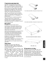
Page 21: ... 備用電源供應器便立即被觸發 啟動 讓交換器及介接設備可持續提供服務 此舉將可提供更高信任度的網路基礎架構 並保 護單一設備因電源供應器故障導致整個網路癱瘓 的窘境 產品描述 D Link 設計 DPS 200A DPS 500A DPS 500DC及 DPS 700備用電源供應器 可依交換器電源功率需 求選擇符合的備用電源供應器 DPS 200A DPS 500A與DPS 500DC使用14 Pin 的DC電源線來連接交換器 DPS 700則是使用的 22 Pin DC電源線 三孔AC電源線為一般標準 可 連接至備援電源供應器的主要電源插座上 14 pin DC 電源線 22 pin DC 電源線 獨立備援電源供應器 DPS 200A DPS 500A DPS 500DC 獨立備援電源供應器 DPS 700 安裝備用電源供應器 RPS DPS 200A 500A 及500DC獨立式備用電...

Page 22: ...C電源線來連接DPS 700與交 換器 假如使用14 Pin DC電源線來取代正確的22 Pin DC電源線 可能導致設備的損壞 電源連接 連接交流電源 DPS 200A 500A 700 以標準 AC 電源連接線連接至 AC 電源插座 在DPS 200A DPS 500A DPS 700 前面板 LED 狀態顯示燈號 為綠色 即表示連結成功 連結 DC 電源 DPS 500DC 1 確實將 DC 電源線連接至備用電源供應器集線裝 置正負極 負極 連接至 48V 接頭 正極 連接至 48V RTN 接頭 建議將接地線連結在集線裝置中間接頭 2 鎖緊連結螺絲 確保連接無誤 連結備用電源供應器 交換器無須更動任何設定 產品規格 型號 DPS 200A DPS 500A 輸入電壓 100 to 240 V AC 100 to 240V AC 輸入頻率 50 60 Hz 50 60 Hz 輸入電流...

Page 23: ...D 8 N C 9 N C 10 RPS Present 11 N C 12 N C 13 PWR Good 14 GND 輸出端腳位 DPS 700 Pin DPS 700 1 54Vrtn 2 54V 3 12 V 4 12 V 5 12 V 6 12 V 7 GND 8 12VRTNsen 9 LS 54V 10 54V 11 54Vrtn 12 GND 13 N C 14 RPS_Present 15 Status 1 16 Status 2 17 RPS_ Power Good 18 GND 19 12VRTNsen 20 LS 12V 21 54Vsen 22 54VRTNsen 更多資訊 透過聯繫列於使用者手冊背面或D Link網站上的 D Link辦公室 您可得到更多的協助資訊 若您要 了解更多關於D Link產品或銷售資訊 請拜訪D Link 網站 http www dl...

Page 24: ...nd damage to the device and other equipment observe the following precautions Power Sources Observe and follow service markings Do not push any objects into the openings of your device unless consistent with the authorized operation of the device Doing so can cause a fire or an electrical shock by shorting out interior components The powering of this device must adhere to the power specifications ...

Page 25: ...local Modificar o alterar el dispositivo Retirar la identificación del producto u otras notificaciones incluyendo las notificaciones de copyright y marcado de patente si fuera el caso Para reducir el riesgo de lesiones personales descargas eléctricas incendios y daños al aparato y otro equipamiento tome las siguientes precauciones Fuentes de alimentación Lea y siga atentamente las instrucciones de...

Page 26: ...nte sujetos al equipo Evite las detenciones repentinas y las superficies irregulares Medio Ambiente No utilice este aparato cerca del agua por ejemplo cerca de una bañera fregadero lavadero peceras en un sótano húmedo o cerca de una piscina No utilice este dispositivo en lugares con alta humedad Este dispositivo no debe ser sometido al agua o la condensación Mantenga el dispositivo alejado de radi...

Page 27: ...de nuestros productos y embalajes ecológicos visite el sitio www dlinkgreen com La presenza di questo simbolo sul prodotto o sulla confezione del prodotto indica che in conformità alle leggi e alle normative locali questo prodotto non deve essere smaltito nei rifiuti domestici ma avviato al riciclo Una volta terminato il ciclo di vita utile portare il prodotto presso un punto di raccolta indicato ...

Page 28: ...ä ja hyvinvointia D Link ja ympäristö D Link ymmärtää ympäristönsuojelun tärkeyden ja on sitoutunut vähentämään tuotteistaan ja niiden valmistuksesta ympäristölle mahdollisesti aiheutuvia haittavaikutuksia Nämä negatiiviset vaikutukset minimoidakseen D Link suunnittelee ja valmistaa tuotteensa mahdollisimman ympäristöystävällisiksi käyttämällä kierrätettäviä alhaisia pitoisuuksia haitallisia ainei...

Page 29: ...29 NOTES ...

Page 30: ...NOTES ...

Page 31: ...31 NOTES ...

Page 32: ...Ver 1 10 DI _130x183 2015 01 15 10 0003 0002 ...

Reviews: