Introduction
A redundant power supply provides a low-cost, simple
solution to the equally simple yet vexing problem of internal
power supply failure, which can result in the shutdown of a
single switching device or an entire network.
With a redundant power supply connected, an integrated
detection circuit continuously monitors the switch’s internal
power supply. In the event of a power interruption, the
redundant power supply is immediately triggered so that the
switch and connected devices can continue providing
service.
This results in a more reliable network infrastructure and
protects the network from a single failure of a network
device power supply.
Description
The DPS-200, DPS-300, DPS-500, DPS-500DC and DPS-
600 are redundant power supply units designed to conform
to the wattage requirements of the switches being
supported. DPS-200 operates at 60 watts, DPS-300
operates at 90 watts, DPS-500/500DC at 140 watts, and
DPS-600 at 500watts.
The DPS-200, DPS-300, DPS-500, DPS-500DC, and DPS-
600 can connect to the master switch using a 14-pin DC
power cable. A standard, three-pronged AC power cable
connects the redundant power supply to the main power
source.
Single RPS (DPS-200/DPS-300 /DPS-500/DPS-500DC)
Single RPS (DPS-600)
14-pin DC power cable
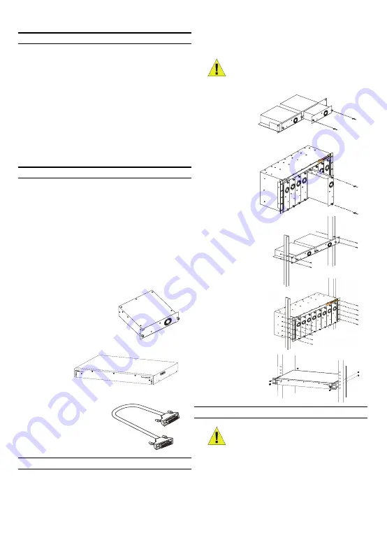
Installation of the RPS
The single RPS DPS-200, 300, 500, and 500DC can be
installed to the standard rack via the RPS rack DPS-800
and DPS-900. DPS-900 is a standard-size rack mount (5U
in height) designed to hold up to 8 redundant power
supplies. The DPS-800 is also a standard-size rack mount
(1.25U in height) designed to hold up to 2 redundant power
supplies. Installed RPS units can be DPS-200s, DPS-300s,
DPS-500s, DPS-500DCs, or a combination of the above.
Inserting a single
RPS into a DPS-
800 RPS rack
Inserting a single
RPS into a DPS-
900 RPS rack
Installing a DPS-800 in a
standard electronics rack
Installing a DPS-900 in
a standard electronics
rack
Installing a DPS-600 in a
standard electronics
rack
Connection
Insert one end of the 14-pin DC power cable into the
receptacle on the switch and the other end into the
redundant power supply.
NOTE:
The DPS-500DC can only be inserted
into a DPS-800
Caution:
The redundant power supply should
be disconnected from its power source before
connecting to the switch. Directly connecting
a powered RPS to the switch may cause
damage to the switch’s internal power supply.
Summary of Contents for DPS-500DC
Page 1: ......
Page 16: ...Second Edition September 2007 6RPSQML 03G RECYCLABLE ...


