4
Hardware Description
Front Panel
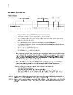
Power Indicator: Green light indicates a normal power supply.
Run Indicator: Blinking green light indicates normal operation.
Alarm Indicator: When the system starts up, the red light will blink. It also indicates the
gateway’s abnormal operation.
P1 – P4 stands for Port 1 – Port 4: Connected to your analog telephone
L1 – L4 stands for Port 5 – Port 8: Connected to your original telephone line on the wall
jack with RJ-11 cable.
WAN stands for the WAN Port Indicator.
L1 – L4 stands for the LAN Port Indicator.
When starting up the system, the Alarm, Run, and Power indicators will light up. After
about 40 seconds, the Alarm indicator will go off, the Run indicator will blink in green,
and the Power indicator will stay green under normal operational conditions. If the
Alarm indicator continues to blink, it means the system is currently communicating
with ISP and has yet to obtain an IP address.
When the WAN is connected, the WAN indicator will light up in green and if data is
being transmitted over the Internet, the indicator blinks in green and orange.
Restore to factory default: (IP address, User’s. Name and Password)
(1) Pull off the power plug.
(2) Press reset (do not let go of the reset button).
(3) Plug the plug back into the socket (do not let go of the reset button).
(4) Let go of the reset button after 6 seconds. Factory settings will be restored.
NOTE 1: Do not connect FXS ports to each other. Also, do not connect any FXS port directly to a
PSTN line or internal PBX. These may cause damage to FXS.
NOTE 2: Please use the power adapter comes with VoIP Gateway. If using adapters other than the
one comes with VoIP Gateway, it may cause problems and will affect the warranty of the
product.
WAN, LAN indicators
Voice ports indicators
Status indicators
Summary of Contents for DVG-7044S
Page 1: ...1 DVG 7044S VOIP Gateway User Manual Version 1 0 ...
Page 2: ......
Page 24: ......
Page 29: ...27 DDNS ...
Page 36: ......


