Version 1.00 | 2023/12/18
Page 1: ...Version 1 00 2023 12 18...
Page 2: ...wo conditions 1 This device may not cause harmful interference and 2 this device must accept any interference received including interference that may cause undesired operation CE Mark Warning This eq...
Page 3: ...nstalling the AC Power Cord Retainer 10 Installing the Redundant Power Supply RPS 12 Connecting the DPS 500A RPS to the Switch 12 4 Switch Connections 14 Stacking the Switch 14 Switch to Switch 17 Swi...
Page 4: ...Layer 3 Stackable Managed Switch Hardware Installation Guide iv Pr cautions de s curit 32 General Precautions for Rack Mountable Products 34 Protecting Against Electrostatic Discharge 35 Warranty Tech...
Page 5: ...e Switch throughout this manual Typographical Conventions Convention Description Boldface Font This convention is used to emphasize keywords It also denotes a button toolbar icon menu or menu items Fo...
Page 6: ...r inactive links and by allowing ports to autonomously enter a hibernated state This intelligent approach ensures efficiency and sustainability Switch Series The following switches are part of the DXS...
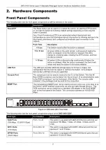
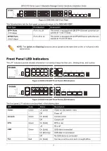
Page 7: ...s additional storage space for firmware images and configuration files that can be copied to and from the Switch Only endpoint devices like USB flash drives are supported Console Port The console port...
Page 8: ...at the same time on the SFP28 ports in this switch series Front Panel LED Indicators The LED indicators provide valuable information in a variety of ways like their color blinking times and location F...
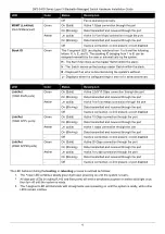
Page 9: ...ived through the port Amber On Solid Active 100 1000 Mbps connection through the port On Blinking Data transmitted and received through the port Off Inactive connection no link present or port disable...
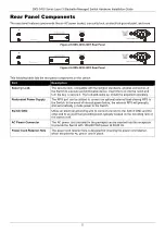
Page 10: ...and cable set should be acquired separately Redundant Power Supply The RPS port can be utilized to connect an optional external load sharing RPS to the Switch In the event of internal power failure t...
Page 11: ...ambient temperature the speed of the fan s will change Fan Mode Fan Status DXS 3410 32XY DXS 3410 32SY Normal mode Ultra Low Below 12 C Below 17 C Very Low Above 15 C Ultra Low to Very Low Below 27 C...
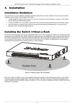
Page 12: ...s section provides guidance for users installing the Switch in a location outside of a Switch rack Affix the provided rubber feet to the underside of the Switch Please be aware that there are designat...
Page 13: ...19 1U rack using the rack mounting kit included in the package contents Fasten the mounting brackets to the sides of the Switch using the screws provided Figure 3 2 Attaching the rack mounting bracke...
Page 14: ...considerable distances While RJ45 wiring connections have a maximum reach of 100 meters fiber optic connections can extend over several kilometers The figure below illustrates the procedure for inser...
Page 15: ...of a power failure as a precautionary measure disconnect the power cord from the Switch After power is restored reconnect the power cord to the Switch s power socket Installing the AC Power Cord Reta...
Page 16: ...tie wrap until the end of the cord Circle the tie of the retainer around the power cord and into the locker of the retainer Figure 3 7 Slide the Retainer through the Tie Wrap Figure 3 8 Circle around...
Page 17: ...Ethernet Switches and it can be linked to the RPS port of the Switch using a 14 pin DC power cable A standard three pronged AC power cable is used to connect the RPS to the main power source CAUTION...
Page 18: ...onfirm the presence and operation of the RPS No software configuration is necessary CAUTION Leave at least 15 cm 6 inches of space at the rear of the Switch when an RPS is installed to prevent cable d...
Page 19: ...nistrators aiming to upgrade their networks leveraging the stacking ports for scaling and stacking purposes This ultimately enhances overall reliability serviceability and availability The Switch supp...
Page 20: ...DXS 3410 Series Layer 3 Stackable Managed Switch Hardware Installation Guide 15 In the following diagram Switches are stacked in the Duplex Chain topology Figure 4 1 Duplex Chain Stacking Topology...
Page 21: ...DXS 3410 Series Layer 3 Stackable Managed Switch Hardware Installation Guide 16 In the following diagram Switches are stacked in the Duplex Ring topology Figure 4 2 Duplex Ring Stacking Topology...
Page 22: ...6 UTP STP cables For 10GBASE T connections to the Switch use Category 6a 7 UTP STP cables For fiber optic connections to the Switch s SFP SFP28 ports make use of the appropriate fiber optic cables Fi...
Page 23: ...DXS 3410 Series Layer 3 Stackable Managed Switch Hardware Installation Guide 18 The diagram below displays a Server connected to the Switch Figure 4 5 Switch to End Node Server...
Page 24: ...offer an in band connection to the CLI using Telnet or SSH NOTE For more information about the CLI refer to the DXS 3410 Series CLI Reference Guide Connecting to the Console Port The Console port is u...
Page 25: ...assword Switch Configuring the IP Address To be able to access the Web UI or the CLI via Telnet SSH we need to know what the IP address of the Switch is The default IP address is 10 90 90 90 with a su...
Page 26: ...nnection to the Web UI using HTTP or HTTPS SSL The Web UI examples in this guide was capture using the Microsoft Edge browser Connecting to the Web UI By default Secure HTTP https access is available...
Page 27: ...witch Hardware Installation Guide 22 The following is a screen capture of the Web User Interface Web UI Figure 5 3 Web User Interface Standard Mode NOTE For more information about the Web UI refer to...
Page 28: ...nagers can view read only information or receive traps using SNMP version 1 while another group can be endowed with higher security levels entailing read write privileges via SNMP version 3 With SNMP...
Page 29: ...r Consumption Maximum DXS 3410 32XY 100 VAC 60 Hz 108 5 Watts 240 VAC 50 Hz 109 0 Watts DXS 3410 32SY 100 VAC 60 Hz 103 5 Watts 240 VAC 50 Hz 104 0 Watts Power Consumption Standby DXS 3410 32XY 100 VA...
Page 30: ...ity Queues Supports the following Maximum of 8 Priority Queues per port Link Aggregation Supports the following Maximum of 32 groups per device Maximum of 8 ports per group Static Routes Supports the...
Page 31: ...auto speed functions are not supported IEEE 802 3x flow control for the full duplex mode All SFP ports are backwards compatible to support SFP transceivers 25G SFP28 Ports Standards IEEE 802 3ae 10GBA...
Page 32: ...m WDM BiDi SFP DEM 436XT BXD 10GBASE LR Single mode 20 km 1330 nm 1270 nm WDM BiDi SFP DEM 436XT BXU 10GBASE LR Single mode 20 km 1270 nm 1310 nm SFP28 DEM S2801SR 25GBASE SR Multi mode 100 m 850 nm S...
Page 33: ...diagrams and tables show the standard RJ45 receptacle connector and their pin assignments Figure B 1 Standard RJ45 port and connector RJ45 Pin Assignment Contact MDI X Port MDI II Port 1 RD receive TD...
Page 34: ...h to access the command line interface The following diagram and table show the standard RJ45 to RS 232cable and pin assignments Figure B 2 Console to RJ45 Cable RJ45 To RS 232 Cable Pin Assignment Ta...
Page 35: ...rmation Only hardware based ERPS supports the Fast Link Drop Interrupt feature with a recovery time of 50 milliseconds in a 16 node ring The distance must be less than 1200 kilometers Model Name ERPS...
Page 36: ...ny objects into the openings of the system Doing so can cause fire or electric shock by shorting out interior components Only use this product with approved equipment Allow the product to cool before...
Page 37: ...pe the Middle East Africa and the Far East CAUTION Risk of Explosion if Battery is replaced by an Incorrect Type Dispose of Used Batteries According to the Instructions ATTENTION Risque d explosion si...
Page 38: ...bles sont quip s de fiches trois broches pour garantir une mise la masse appropri e N utilisez pas d adaptateur de prise et n liminez pas la broche de mise la masse du c ble Si un c ble de rallonge e...
Page 39: ...item in the rack first Make sure that the rack is level and stable before extending a component from the rack Use caution when pressing the component rail release latches and sliding a component into...
Page 40: ...sis The following steps can also be taken prevent damage from electrostatic discharge ESD When unpacking a static sensitive component from its shipping carton do not remove the component from the anti...
Page 41: ...quidators expressly disclaim their warranty obligation pertaining to the product and in that case the product is being sold As Is without any warranty whatsoever including without limitation the Limit...
Page 42: ...pyright Statement No part of this publication or documentation accompanying this product may be reproduced in any form or by any means or used to make any derivative such as translation transformation...
Page 43: ...egistration Register your D Link product online at http support dlink com register Product registration is entirely voluntary and failure to complete or return this form will not diminish your warrant...
Page 44: ...nfiguration Please refer to the user manual to learn more or visit http www mydlink com for more information Also feel free to contact us U S and Canadian customers can contact D Link Technical Suppor...
Page 45: ...ASSISTANCE TECHNIQUE ASISTENCIA T CNICA SUPPORTO TECNICO TECHNISCHE ONDERSTEUNING POMOC TECHNICZNA TECHNICK PODPORA TECHNIKAI T MOGAT S TEKNISK ST TTE TEKNISK SUPPORT TEKNINEN TUKI TEKNISK SUPPORT ASS...
Page 46: ...donesia www dlink co id Malaysia www dlink com my Philippines www dlink com ph Vietnam www dlink com vn Korea customers Tel 1899 3540 Monday to Friday 9 30am to 6 30pm Web http d link co kr E mail sup...
Page 47: ...enter no 202 25866777 General Inquiries info eg me dlink com Kingdom of Saudi Arabia Riyadh Saudi Arabia E Mail info sa me dlink com Pakistan Karachi Office D 147 1 KDA Scheme 1 Opposite Mudassir Park...
Page 48: ...D Link D Link D Link D Link D Link 8 800 700 5465 http www dlink ru e mail support dlink ru 114 3 289 390043 16 7 4912 503 505...
Page 49: ...375 17 218 13 65 E mail support dlink by c 143 7 727 378 55 90 E mail almaty dlink ru 3 23 5 374 10 39 86 67 info dlink am Lietuva Vilnius irm n 139 303 Tel 370 5 236 36 29 E mail info dlink lt Eesti...
Page 50: ...inkla com soporte call center Soporte T cnico de D Link a trav s de Internet Horario de atenci n Soporte T cnico en www dlinkla com e mail soporte dlinkla com consultas dlinkla com Clientes de Brasil...
Page 51: ...nk D Link D Link 0800 002 615 02 6600 0123 8715 http www dlink com tw dssqa_service dlink com tw http www dlink com tw D Link http www dlink com hk http www dlink com hk contact html D Link www dlink...
Page 52: ...us web D Link Dukungan Teknis untuk pelanggan Tel 0800 14014 97 Layanan Bebas Pulsa Dukungan Teknis D Link melalui Internet Pertanyaan Umum sales id dlink com Bantuan Teknis support id dlink com Websi...
Page 53: ...site 1 employee 2 9 10 49 50 99 100 499 500 999 1000 or more 3 What network protocol s does your organization use XNS IPX TCP IP DECnet Others_____________________________ 4 What network operating sys...
Page 54: ......