

Summary of Contents for EasySmart DGS-1100-24
Page 1: ...Ver 1 00 ...
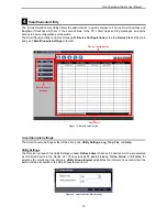
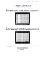
Page 36: ...D Link EasySmart Switch User Manual Figure 57 Security Dynamic Forwarding Table 33 ...
Page 40: ......
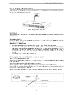
The D-Link EasySmart DGS-1100-24 is a high-performance network switch designed for small to medium-sized businesses. With its user-friendly interface, this product allows for seamless network management. Find the manual for the D-Link EasySmart DGS-1100-24 free to download from our website, providing you with all the necessary instructions for optimal usage.
Page 1: ...Ver 1 00 ...
Page 36: ...D Link EasySmart Switch User Manual Figure 57 Security Dynamic Forwarding Table 33 ...
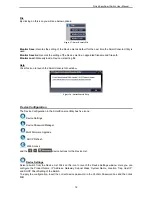
Page 40: ......


