4
D-Link NetDefend Firewall
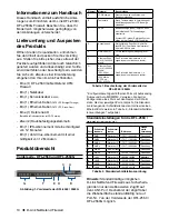
Item
Description
Model Name:
Device model name
System Status:
System function status
CPU Load:
Connections:
CPU utilization and concurrent
sessions
Total BPS:
Concurrent traffic per second
Total PPS:
Concurrent packets per second
Date:
Current device date
Time:
Current device time
Uptime:
The amount of time since last
restart
Mem:
System memory utilization
IDS Sigs:
IDS signature information
Interface Name:
(See Table 4.)
IP address for each interface
Core Version:
Current firmware version
CPU Temp.
System Temp.
CPU and system temperature via
on board sensor
Fan Status
Fan speed
Installing and Connection
Installing Equipment
This chapter describes how to install a
DFL-2560/DFL-2560G device in a standard
19-inch equipment rack and how to connect
network and power cables to the device.
Before You Begin
Observe the following precautions to help
prevent faults, equipment failures and injuries:
Before installation, always disconnect the
-
power supply.
Ensure that the room in which you operate
-
the device has adequate air circulation and
that the room temperature does not exceed
40˚C (104˚F).
Allow 1 meter (3 feet) of clear space from the
-
front and back of the device.
Do not place the device in an equipment rack
-
frame that blocks the air vents on the sides of
the chassis. Ensure that enclosed racks have
fans and vented sides.
Correct any of the following hazardous
-
conditions before any installation: moist or
wet floors, leaks, ungrounded/frayed power
cables, or missing safety grounds.
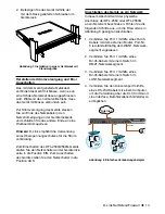
You can mount the DFL-2560/DFL-2560G
device into a standard 19-inch equipment rack.
To install an DFL-2560/DFL-2560G device into
a rack:
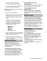
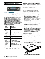
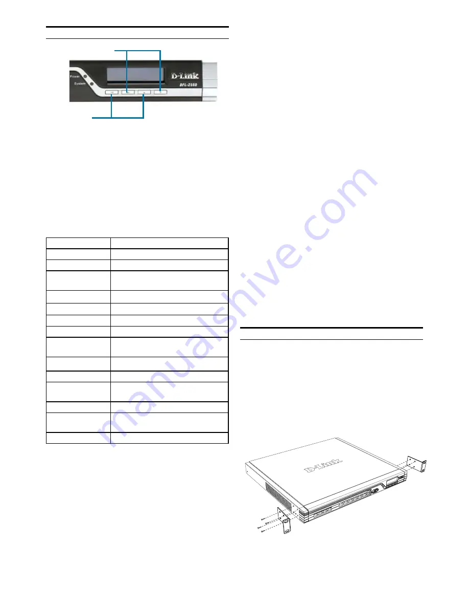
1. Attach the mounting brackets to each side
of the chassis as shown in figure 6 and
secure them with the provided screws.
Figure 6. Attaching Rack Mount Brackets
Table 4. Device Status Shown on LCD Panel
Once the DFL-2560/2560G has completed its
system startup routine, the LCD panel will be
ready to display the device status information.
You can use the keypad to select a desired
display option. The following table lists the
status information that can be displayed on the
firewall’s LCD panel.
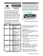
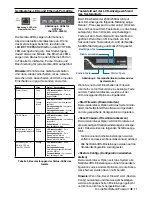
Figure 5. Button Definitions (After Boot-up)
LCD Keypad Controls After Boot-up
Next Button
Back Button
Summary of Contents for NetDefend DFL-2560
Page 8: ......
Page 16: ......
Page 24: ......
Page 32: ......
Page 41: ...D Link NetDefend Firewall 41 NOTES ...
Page 42: ...42 D Link NetDefend Firewall NOTES ...


