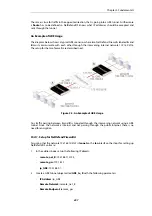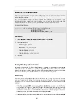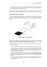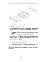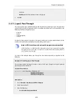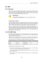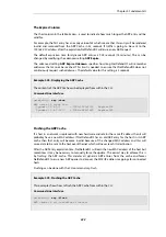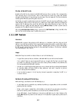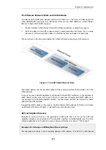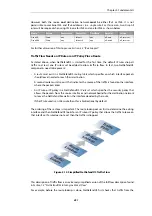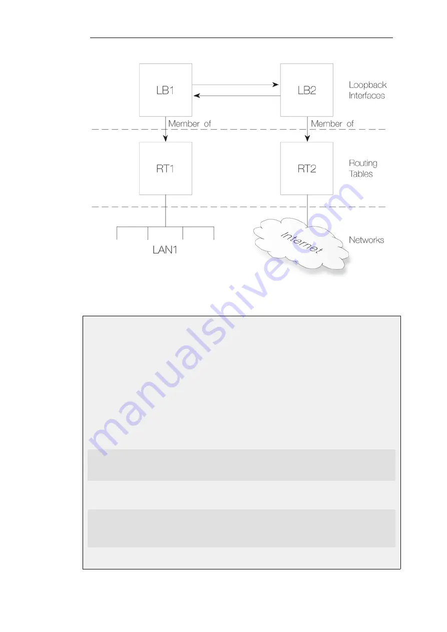
Figure 3.10. Components of Loopback Interface Setup
Example 3.25. Creating a Loopback Interface Pair
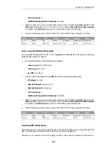
This example shows how to create a loopback interface pair called
LB1
belonging to the
RT1
routing table and
LB2
belonging to the
RT2
routing table.
LB1
will have the IPv4 address
127.0.6.1
and network
127.0.6.0/24
.
LB2
will have the IPv4 address
127.0.5.1/24
and network
127.0.5.0/24
.
Traffic routed by the
RT1
table into the
LB1
interface will now exit on the
LB2
interface and be
then routed using the
RT2
routing table.
Command-Line Interface
A. Create the first loopback interface:
gw-world:/> add Interface LoopbackInterface LB1
IP=127.0.5.1
Network=127.0.5.0/24
MemberOfRoutingTable=RT1
B. Create the second loopback interface:
gw-world:/> add Interface LoopbackInterface LB2
IP=127.0.6.1
Network=127.0.6.0/24
LoopTo=LB1
MemberOfRoutingTable=RT2
Chapter 3: Fundamentals
217
Summary of Contents for NetDefendOS
Page 30: ...Figure 1 3 Packet Flow Schematic Part III Chapter 1 NetDefendOS Overview 30 ...
Page 32: ...Chapter 1 NetDefendOS Overview 32 ...
Page 144: ...Chapter 2 Management and Maintenance 144 ...
Page 284: ...Chapter 3 Fundamentals 284 ...
Page 392: ...Chapter 4 Routing 392 ...
Page 419: ... Host 2001 DB8 1 MAC 00 90 12 13 14 15 5 Click OK Chapter 5 DHCP Services 419 ...
Page 420: ...Chapter 5 DHCP Services 420 ...
Page 573: ...Chapter 6 Security Mechanisms 573 ...
Page 607: ...Chapter 7 Address Translation 607 ...
Page 666: ...Chapter 8 User Authentication 666 ...
Page 775: ...Chapter 9 VPN 775 ...
Page 819: ...Chapter 10 Traffic Management 819 ...
Page 842: ...Chapter 11 High Availability 842 ...
Page 866: ...Default Enabled Chapter 13 Advanced Settings 866 ...
Page 879: ...Chapter 13 Advanced Settings 879 ...

