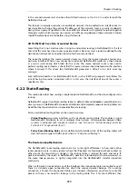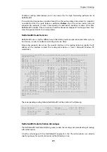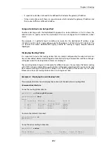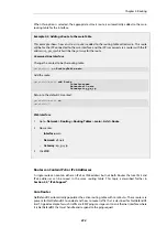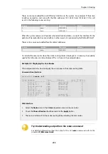
There is one route added for each Ethernet interface in the system. For example, if there two
interfaces named lan and wan with the IPv4 addresses
192.168.0.10
and
193.55.66.77
, this will
result in the following routes existing:
Route #
Interface
Destination
Gateway
1
core
192.168.0.10
2
core
193.55.66.77
When the system receives an IP packet whose destination address is one of the interface IPs, the
packet will be routed to the core interface. In other words, it is processed by NetDefendOS itself.
There is also a core route added for all multicast addresses:
Route #
Interface
Destination
Gateway
1
core
224.0.0.0/4
To include the core routes when the active routing table is displayed, it is necessary to explicitly
specify that all routes are to be displayed. This is shown in the example below.
Example 4.3. Displaying the Core Routes
This example illustrates how to display the core routes in the active routing table.
Command-Line Interface
gw-world:/> routes -all
Flags Network
Iface
Gateway
Local IP Metric
----- ------------------ ---------- ------------- -------- ------
127.0.0.1
core
(Shared IP)
0
192.168.0.1
core
(Iface IP)
0
213.124.165.181
core
(Iface IP)
0
127.0.3.1
core
(Iface IP)
0
127.0.4.1
core
(Iface IP)
0
192.168.0.0/24
lan
0
213.124.165.0/24
wan
0
224.0.0.0/4
core
(Iface IP)
0
0.0.0.0/0
wan
213.124.165.1
0
Web Interface
1.
Select the Routes item in the Status dropdown menu in the menu bar
2.
Check the Show all routes checkbox and click the Apply button
3.
The main window will list the active routing table, including the core routes
Tip: Understanding output from the routes command
For detailed information about the output of the CLI
routes
command, refer to the
separate
CLI Reference Guide
.
Chapter 4: Routing
295
Summary of Contents for NetDefendOS
Page 30: ...Figure 1 3 Packet Flow Schematic Part III Chapter 1 NetDefendOS Overview 30 ...
Page 32: ...Chapter 1 NetDefendOS Overview 32 ...
Page 144: ...Chapter 2 Management and Maintenance 144 ...
Page 284: ...Chapter 3 Fundamentals 284 ...
Page 392: ...Chapter 4 Routing 392 ...
Page 419: ... Host 2001 DB8 1 MAC 00 90 12 13 14 15 5 Click OK Chapter 5 DHCP Services 419 ...
Page 420: ...Chapter 5 DHCP Services 420 ...
Page 573: ...Chapter 6 Security Mechanisms 573 ...
Page 607: ...Chapter 7 Address Translation 607 ...
Page 666: ...Chapter 8 User Authentication 666 ...
Page 775: ...Chapter 9 VPN 775 ...
Page 819: ...Chapter 10 Traffic Management 819 ...
Page 842: ...Chapter 11 High Availability 842 ...
Page 866: ...Default Enabled Chapter 13 Advanced Settings 866 ...
Page 879: ...Chapter 13 Advanced Settings 879 ...

