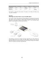
located on the same local network as well as clients on the external, unprotected side.
Communication can take place across the public Internet or between clients on the local
network.
•
Scenario 3
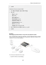
Protecting proxy and local clients - Proxy on a DMZ interface
The SIP session is between a client on the local, protected side of the NetDefend Firewall and
a client which is on the external, unprotected side. The SIP proxy is located on the DMZ
interface and is physically separated from the local client network as well as the remote client
network and proxy network.
All the above scenarios will also deal with the situation where two clients in a session reside on
the same network.
These scenarios will now be examined in detail.
Scenario 1
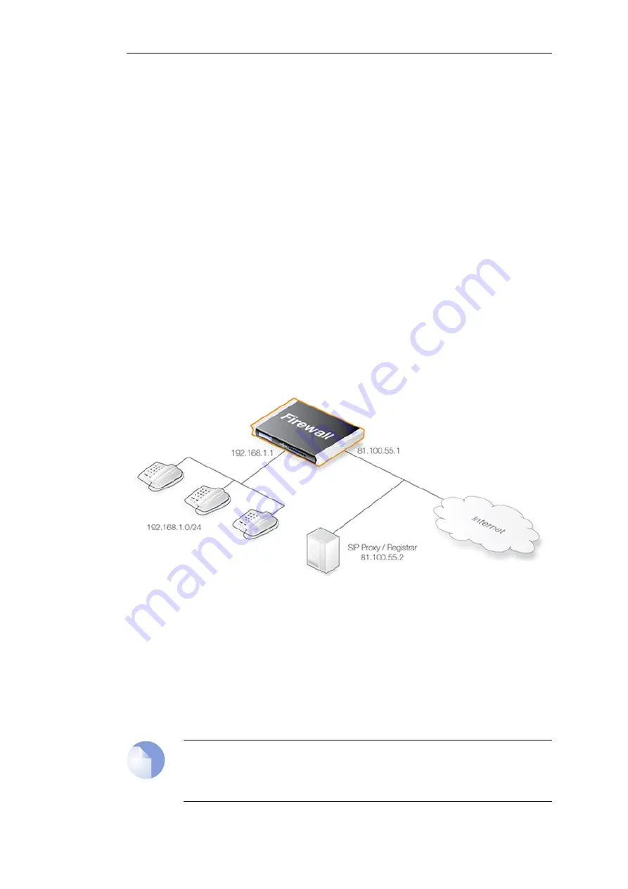
Protecting local clients - Proxy located on the Internet
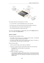
The scenario assumed is an office with VoIP users on a private internal network where the
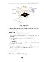
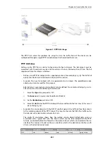
network's topology will be hidden using NAT. This is illustrated below.
The SIP proxy in the above diagram could alternatively be located remotely across the Internet.
The proxy should be configured with the Record-Route feature enabled to ensure all SIP traffic
to and from the office clients will be sent through the SIP Proxy. This is recommended since the
attack surface is minimized by allowing only SIP signaling from the SIP Proxy to enter the local
network.
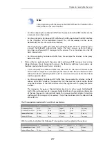
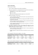
This scenario can be implemented in two ways:
•
Using NAT to hide the network topology.
•
Without NAT so the network topology is exposed.
Note: NAT traversal should not be configured
SIP User Agents and SIP Proxies should not be configured to employ NAT Traversal in any
setup. For instance the
Simple Traversal of UDP through NATs
(STUN) technique
Chapter 6: Security Mechanisms
468
Summary of Contents for NetDefendOS
Page 30: ...Figure 1 3 Packet Flow Schematic Part III Chapter 1 NetDefendOS Overview 30 ...
Page 32: ...Chapter 1 NetDefendOS Overview 32 ...
Page 144: ...Chapter 2 Management and Maintenance 144 ...
Page 284: ...Chapter 3 Fundamentals 284 ...
Page 392: ...Chapter 4 Routing 392 ...
Page 419: ... Host 2001 DB8 1 MAC 00 90 12 13 14 15 5 Click OK Chapter 5 DHCP Services 419 ...
Page 420: ...Chapter 5 DHCP Services 420 ...
Page 573: ...Chapter 6 Security Mechanisms 573 ...
Page 607: ...Chapter 7 Address Translation 607 ...
Page 666: ...Chapter 8 User Authentication 666 ...
Page 775: ...Chapter 9 VPN 775 ...
Page 819: ...Chapter 10 Traffic Management 819 ...
Page 842: ...Chapter 11 High Availability 842 ...
Page 866: ...Default Enabled Chapter 13 Advanced Settings 866 ...
Page 879: ...Chapter 13 Advanced Settings 879 ...

