background image

5  Configuration


D-Link Web Smart Switch User Manual


Figure 44 – Device Information 


System > System Settings 

The System Setting allows the user to configure the IP address and the basic system information of the 
Switch. 


IP Information: 

There are two ways for the switch to obtain an IP address: Static and DHCP (Dynamic Host 

Configuration Protocol). 

When using static mode, the 

IP Address

Subnet Mask

 and 

Gateway

 can be manually configured. When 

using DHCP mode, the Switch will first look for a DHCP server to provide it with an IP address (including 
network mask and default gateway) before using the default or previously entered settings. By default the IP 
setting is static mode with IP address is 

10.90.90.90

 and subnet mask is 

255.0.0.0


System Information: 

By entering a 

System Name

 and 

System Location

, the device can more easily be 

recognized through the SmartConsole Utility and from other Web-Smart devices on the LAN.  


Login Timeout:

 The Login Timeout controls the idle time-out period for security purposes, and when there is 

no action for a specific time span in the Web-based Management. If the current session times out (expires), 
the user is required a re-login before using the Web-based Management again. Selective range is from 3 to 
30 minutes, and the default setting is 5 minutes. 


Group Interval:

 The D-Link Web Smart Switch will routinely send report packets to the SmartConsole Utility 

in order to maintain the information integrity. The user can adjust the 

Group Interval

 to optimal frequency. 

Selective range is from 120 to 1225 seconds, and 0 means disabling the reporting function. 


Figure 45 – System > System Setting 


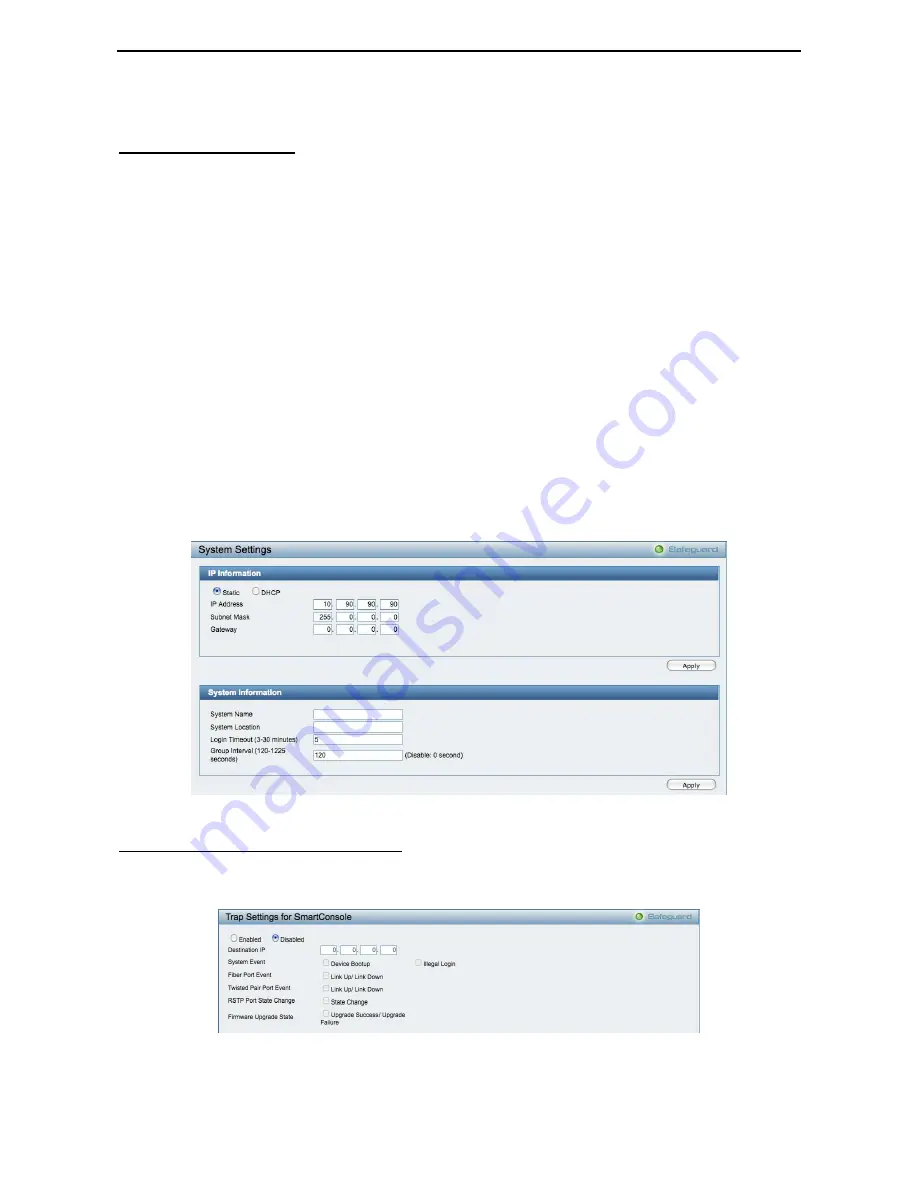
System > Trap Settings For SmartConsole 

By configuring the Trap Setting, it allows SmartConsole Utility to monitor specified events on this Web-Smart 
Switch. By default, Trap Setting is disabled. When the Trap Setting is enabled, enter the 

Destination IP


address of the managing station that will receive trap information. 


Figure 46 – System > Trap Setting 


You can select which event message(s) will be sent to the managing station 

28 

Summary of Contents for Web Smart Switch DGS-1210-16

Page 1: ......

Page 2: ...allation 6 Step 3 Plugging in the AC Power Cord 7 Power Failure 8 Getting Started 9 Management Options 9 Using Web based Management 9 Supported Web Browsers 9 Connecting to the Switch 9 Login Web base...

Page 3: ...OUI Setting 36 Configuration Link Aggregation Port Trunking 37 Configuration Link Aggregation LACP Port Settings 37 Configuration IGMP Snooping 38 Configuration Port Mirroring 39 Configuration Power S...

Page 4: ...h 61 Config account admin password 62 Save 62 Appendix A Ethernet Technology 63 Gigabit Ethernet Technology 63 Fast Ethernet Technology 63 Switching Technology 63 Appendix B Technical Specifications 6...

Page 5: ...s Usage In this guide the term Switch first letter capitalized refers to the Smart Switch and switch first letter lower case refers to other Ethernet switches Some technologies refer to terms switch b...

Page 6: ...m normal data traffic Asymmetric VLAN is implemented in these switches for a more efficient use of shared resources such as server or gateway devices Network Security D Link s innovative Safeguard Eng...

Page 7: ...running on 1000M NOTE On DGS 1210 16 the SFP ports are shared with normal RJ 45 ports 13 to 16 When optical transceiver is inserted to SFP port and link up the RJ 45 port cannot be used Reset By pres...

Page 8: ...ports for optical transceivers Figure 5 DGS 1210 48 Front Panel Power LED The Power LED lights up when the Switch is connected to a power source Port Link Act Speed LED 1 44 45F 46F 47F 48F 45T 46T 47...

Page 9: ...1 Product Introduction D Link Web Smart Switch User Manual Rear Panel Figure 6 DGS 1210 48 Rear Panel Power Connect the supplied AC power cable to this port 5 5...

Page 10: ...ch installation and operation it is recommended that you Visually inspect the power cord to see that it is secured fully to the AC power connector Make sure that there is proper heat dissipation and a...

Page 11: ...operation of the equipment is not compromised C Mechanical Loading Mounting of the equipment in the rack should be such that a hazardous condition is not achieved due to uneven mechanical loading D C...

Page 12: ...tion D Link Web Smart Switch User Manual Figure 10 Plugging the switch into an outlet Power Failure As a precaution the switch should be unplugged in case of power failure When power is resumed plug t...

Page 13: ...ing the SmartConsole Utility you do not need to change the IP address of your PC and it is easier to initialize multiple Smart Switches Please refer to the following installation instructions for the...

Page 14: ...ears in the Monitor List This will automatically load the web configuration in your web browser When the following logon dialog box appears enter the password then click OK The default password is adm...

Page 15: ...d use the SmartConsole Utility to discover the Smart Switches Option 2 Follow these steps to install the SmartConsole Utility manually 1 Insert the Utility CD into your CD Rom DVD Rom Drive 2 From the...

Page 16: ...ettings Device List Figure 14 SmartConsole Utility SmartConsole Settings The SmartConsole Settings at the left has five icons Utility Settings Log Trap File and Help Utility Settings Click this icon t...

Page 17: ...e 16 SmartConsole Log Trap Click this icon to launch the Trap window Click View Trap to show the events of the SmartConsole Utility and the device Date Time indicates when the trap message was receive...

Page 18: ...of the Device List as default for the next time the SmartConsole Utility is used Monitor Save As Records the setting of the Device List in an appointed filename and file path Monitor Load Manually loa...

Page 19: ...tons for the Device List Device Settings Select a switch from the Device List Click on this icon to launch the Device Settings window Here you can configure the Product Name IP Address Gateway Subnet...

Page 20: ...rect password of the device and then click Upgrade The state will show OK after completion or Fail if the firmware upgrade fails or cannot be completed for any reason Figure 22 Firmware Upgrade CAUTIO...

Page 21: ...nd click the button to remove it Figure 24 SmartConsole Add device Figure 25 SmartConsole Delete device Device List This list displays all discovered Web Smart devices on the network Figure 26 SmartCo...

Page 22: ...t Mask Displays the Subnet Mask setting of the device Gateway Displays the Gateway setting of the device Device Group Interval Displays the intervals in seconds that the Switch will be discovered in t...

Page 23: ...Web Smart Switch If you do not plan to change anything click Exit to leave the Wizard and enter the Web Interface You can also skip it by clicking Don t show Smart Wizard next time for the next time...

Page 24: ...nterface The default SNMP Setting is Disabled Click Enabled enter Community names and then click Apply to make it effective Read_Only Community Read only privilege allows authorized management station...

Page 25: ...elect DHCP to have the switch obtain an IP address from a DHCP server in the network Figure 29 Configure System IP address in Smart Wizard NOTE Changing the system IP address will disconnect you from...

Page 26: ...y choosing different functions in the Function Tree you can change all the settings in the Main Configuration Screen The main configuration screen will show the current status of your Switch by clicki...

Page 27: ...n view or edit the log file by using text editor e g Notepad Figure 34 Save Log Tool Bar Tool Menu The Tool Menu offers global function controls such as Reset Reset System Reboot Device Configuration...

Page 28: ...ent settings to your disk Click Browse to browse your inventories for a saved backup settings file Click Restore after selecting the backup settings file you want to restore TFTP TFTP Trivial File Tra...

Page 29: ...k Backup to save the firmware to the TFTP server Click Upgrade after selecting the firmware file you want to restore CAUTION Do not disconnect the PC or remove the power cord from device until the upg...

Page 30: ...5 Configuration D Link Web Smart Switch User Manual Figure 42 User Guide Micro Site 26...

Page 31: ...iguration Spanning Tree STP Global Settings Default is disabled Port Mirroring Click Setting to link to Configuration Port Mirroring Default is disabled Storm Control Click Setting to link to Configur...

Page 32: ...n Timeout The Login Timeout controls the idle time out period for security purposes and when there is no action for a specific time span in the Web based Management If the current session times out ex...

Page 33: ...pport 100M Full Force Mode 100M Half Force Mode or Disabled The default setting for all ports is Auto NOTE Be sure to adjust port speed settings appropriately after changing the connected cable media...

Page 34: ...P Setting Community Setting In support of SNMP version 1 the Web Smart Switch accomplishes user authentication by using Community Settings that function as passwords The remote user SNMP application a...

Page 35: ...nd the default value is 514 Time Stamp Select Enable to time stamp log messages Severity Specifies the minimum severity from which warning messages are sent to the server There are three levels When a...

Page 36: ...w VLAN without having to change any physical connections The IEEE 802 1Q VLAN Configuration page provides powerful VID management functions The original settings have the VID as 1 no default name and...

Page 37: ...d in a small network where a L3 routing device is absent or if the resource to be shared is not capable of supporting tagged VLAN for example a printer The example below is a typical application of As...

Page 38: ...e other VLANs for example port 6 and 7 respectively Therefore we have three VLANs that share some common ports but their original membership ports are still separated from each other for example port...

Page 39: ...Q Management VLAN Configuration Voice VLAN Voice VLAN Setting Voice VLAN is a feature that allows you to automatically place the voice traffic from IP phone to an assigned VLAN to enhance the VoIP ser...

Page 40: ...mpacted by the QoS feature Configuration Voice VLAN Voice VLAN OUI Setting This window allows the user to configure the user defined voice traffic s OUI An Organizationally Unique Identifier OUI is th...

Page 41: ...s enabled on the device LACP allows for the automatic detection of links in a Port Trunking Group Disable Remove all members in this trunk group Figure 63 Configuration Link Aggregation Port Trunking...

Page 42: ...connections that have group members attached The settings of IGMP snooping is set by each VLAN individually Figure 65 Configuration IGMP Snooping Configuration By default IGMP is disabled If enabled t...

Page 43: ...Default is 10 seconds Querier State D Link Smart Switch is able to send out the IGMP Queries to check the status of multicast clients Default is disabled To enable IGMP snooping for a given VLAN selec...

Page 44: ...e reduces power consumption automatically when the RJ 45 port is link down or the connected devices are turned off Less power will be consumed also when the short cable is used less than 20 meters By...

Page 45: ...Port The ending of a consecutive group of ports may be configured starting with the selected port State Use the drop down menu to toggle between Enabled and Disabled Default is Disabled Click Apply t...

Page 46: ...ylight Saving Time State Use this drop down menu to enable or disable the DST Settings Daylight Saving Time Offset in Minutes Use this drop down menu to specify the amount of time that will constitute...

Page 47: ...32768 TX Hold Count 1 10 Used to set the maximum number of Hello packets transmitted per interval The count can be specified from 1 to 10 The default is 6 Maximum Age 6 40 sec This value may be set to...

Page 48: ...able STP by per port based It will be selectable after the global STP is enabled External Cost This defines a metric that indicates the relative cost of forwarding packets to the specified port list P...

Page 49: ...rue and False to set the restricted role state of the packet If set to True the port will never be selected to be the Root port The default value is False Restricted TCN Toggle between True and False...

Page 50: ...the selected ports NOTE The TX rate for Gigabit ports can only be configured in multiples of 1850kbps If any other value is used the system automatically rounds it down to the lower multiple of 1850...

Page 51: ...Priority to process the packets with the highest priority first Select WRR Weighted Round Robin to process packets according to the weight of each priority When a priority level has reached its egres...

Page 52: ...255 255 To delete the IP address simply click the Delete button Check the unwanted address and then click Apply Security Safeguard Engine D Link s Safeguard Engine is a robust and innovative technolog...

Page 53: ...The EAP packet from the RADIUS server also contains the authentication method to be used The client can reject the authentication method and request another depending on the configuration of the clien...

Page 54: ...entication is enabled Default is 3600 To establish 802 1X port specific assignments select the From Ports To Ports and select Enable 802 1X Port Access Control Three type of Port Access Control State...

Page 55: ...earning capability and specifying the static MAC addresses the network is protected from potential threats like hackers because traffic from illegal MAC addresses will not be forwarded by the Switch S...

Page 56: ...atistics of individual ports click one of the linked port numbers for details Figure 86 Monitoring Port Statistics Previous Page Go back to the Statistics main page Refresh To renew the details collec...

Page 57: ...Test Failed means some other errors occurred during cable diagnostics Please select the same port and test again Cable Fault Distance meters Indicates the distance of the cable fault from the Switch p...

Page 58: ...ess The ACL Configuration Wizard will aid with the creation of access profiles and ACL Rules The ACL Wizard will create the access rule and profile automatically The maximum usable profiles are 50 and...

Page 59: ...Enter a range of ports to be configured Press Apply for the settings to take effect NOTE Once the ACL rules conflict rules with the smaller rule ID will take higher priority NOTE Be careful when confi...

Page 60: ...will be displayed 2 Selecting the field of interest will display the related columns in the lower part of the page Enter the filtering mask and click Create when done A filtering mask is to specify t...

Page 61: ...he field of format is xx xx xx xx xx xx Source MAC Address Specify the Source MAC address the field of format is xx xx xx xx xx xx 802 1p Specify the 802 1p priority value Ether Type Specify the Ether...

Page 62: ...ID hyperlink Figure 94 ACL Access Profile List Access Rule List ACL ACL Finder This page is used to help find a previously configured ACL entry To search for an entry enter the profile ID from the dro...

Page 63: ...ser Name and Password to log in The default user name and password is admin Note that the user name and password are case sensitive Press Enter in both the Username and Password fields The command pro...

Page 64: ...erver cfg_toTFTP Specifies that the Switch s current settings will be uploaded to the TFTP server tftp ip address The IP address of the TFTP server filename The filename of the firmware or switch conf...

Page 65: ...the workstation The terminal interface sends five pings to the target station Syntax ping ipaddr Parameter Parameter Description ipaddr The IP address of the target station Reboot This command reboot...

Page 66: ...fig account admin password The command sets the administrator password Syntax config account admin password passwd Parameter Parameter Description passwd The new password of the administrator Save The...

Page 67: ...r unshielded twisted pair UTP cabling a flexible foundation for the next generation of network technology products will be created This will outfit your network with a powerful 1000 Mbps capable backb...

Page 68: ...X TX 1310 RX 1550nm 40km DEM 220T 100Base BX TX 1550 RX 1310nm 20km DEM 220R 100Base BX TX 1310 RX 1550nm 20km Physical Environment AC input 100 240 VAC 50 60Hz internal universal power supply Acousti...

Page 69: ...X port based access control Port Security IP and MAC ACL Broadcast Storm Control D Link Safeguard Engine Trusted Host Management Web based GUI or SmartConsole Utility D Link proprietary CLI SNMP suppo...

Page 70: ...of the equipment in a rack should be such that the amount of air flow required for safe operation of the equipment is not compromised C Mechanical Loading Mounting of the equipment in the rack should...

Page 71: ......

Reviews: