background image

Configuration


D-Link Web Smart Switch User Manual


1

1

7

7


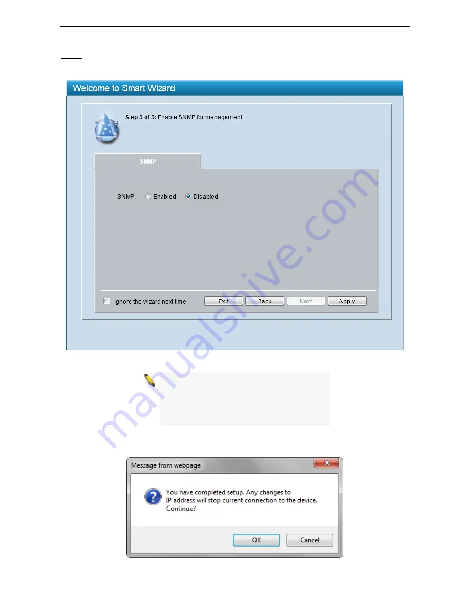
The SNMP Setting allows you to quickly enable or disable the SNMP function. The default SNMP Setting is 

Disabled

. Click 

Enabled

 and then click 

Apply

 to make it effective.  

SNMP 


Figure 4.3 – SNMP in Smart Wizard 


NOTE:

  Changing the system IP address will 

disconnect you from the current connection. 
Please enter the correct IP address in the Web 
browser again and make sure your PC is in the 
same subnet with the switch. See Login Web-
based Management for a detailed description. 


When 

IP Address

 in Step 1 is changed, the following dialog box appears. Click 

OK

 to confirm all settings in 

the Wizard, and start a new web browser. 


Figure 4.4 – Confirm the changes of IP address in Smart Wizard 

Summary of Contents for Web Smart Switch DGS-1210-16

Page 1: ......

Page 2: ...In diesem Fall kann vom Benutzer verlangt werden angemessene Massnahmen zu ergreifen Warnung Este es un producto de Clase A En un entorno doméstico puede causar interferencias de radio en cuyo case puede requerirse al usuario para que adopte las medidas adecuadas Precaución Ceci est un produit de classe A Dans un environnement domestique ce produit pourrait causer des interférences radio auquel ca...

Page 3: ...llation 8 Desktop or Shelf Installation 8 Rack Installation 8 Step 3 Plugging in the AC Power Cord with Power Cord Clip 9 Power Failure 12 3 Getting Started 13 Management Options 13 Using Web based Management 13 Supported Web Browsers 13 Connecting to the Switch 13 Login Web based Management 14 Smart Wizard 14 Web based Management 14 4 Configuration 15 Smart Wizard Configuration 15 IP Information ...

Page 4: ...ng Table 37 L2 Functions Spanning Tree STP Global Settings 38 L2 Functions Spanning Tree STP Port Settings 39 L2 Functions Link Aggregation Port Trunking 41 L2 Functions Link Aggregation LACP Port Settings 41 L2 Functions Multicast IGMP Snooping 42 L2 Functions Multicast MLD Snooping 44 L2 Functions Multicast Multicast Forwarding 46 L2 Functions Multicast Multicast Filtering Mode 47 L2 Functions S...

Page 5: ...NMP Group 83 SNMP SNMP SNMP View 84 SNMP SNMP SNMP Community 84 SNMP SNMP SNMP Host 85 SNMP SNMP SNMP Engine ID 85 SNMP RMON RMON Global Settings 85 SNMP RMON RMON Statistics 85 SNMP RMON RMON History 86 SNMP RMON RMON Alarm 86 SNMP RMON RMON Event 87 Monitoring Port Statistics 88 Monitoring Cable Diagnostics 89 Monitoring System Log 90 5 Command Line Interface 91 To connect a switch via TELNET 91...

Page 6: ...cifications 101 Hardware Specifications 101 Key Components Performance 101 Port Functions 101 Physical Environment 101 Emission EMI Certifications 101 Safety Certifications 101 Features 101 L2 Features 101 L3 Features 101 VLAN 101 QoS Quality of Service 101 AAA 102 ACL 102 Security 102 OAM 102 Management 102 D Link Green Technology 102 ...

Page 7: ... indicates important information that helps a better use of the device A NOTICE indicates either potential damage to hardware or loss of data and tells how to avoid the problem A CAUTION indicates potential property damage or personal injury Safety Instructions Use the following safety guidelines to ensure your own personal safety and to help protect your system from potential damage Throughout th...

Page 8: ... and current marked on the product s electrical ratings label The voltage and current rating of the cable should be greater than the ratings marked on the product To help prevent electric shock plug the system and peripheral power cables into properly grounded electrical outlets These cables are equipped with three prong plugs to help ensure proper grounding Do not use adapter plugs or remove the ...

Page 9: ...e the equipment in the absence of a suitably installed ground conductor Contact the appropriate electrical inspection authority or an electrician if you are uncertain that suitable grounding is available CAUTION The system chassis must be positively grounded to the rack cabinet frame Do not attempt to connect power to the system until grounding cables are connected A qualified electrical inspector...

Page 10: ...ch as streaming multimedia by prioritizing that traffic in network These functions allow switches to work seamlessly with VLAN and 802 1p traffic in the network Auto Surveillance VLAN will automatically place the video traffic from pre defined IP surveillance devices to an assigned VLAN with higher priority so it can be separated from normal data traffic Asymmetric VLAN is implemented in these swi...

Page 11: ...orts should use UL recognized Optical Transceiver product Rated Laser Class I 3 3Vdc Reset By pressing the Reset button for 5 seconds the Switch will change back to the default configuration and all changes will be lost AC LINE 100 240 VAC 50 60 Hz SWITCH GND Power Cord Clip 0 5AMAX Rear Panel Figure 1 2 DGS 1210 16 Rear Panel Power The power port is where to connect the AC power cord Security Loc...

Page 12: ...a secure immovable device Insert the lock into the notch and turn the key to secure the lock The lock and cable apparatus should be purchased separately DGS 1210 48 44 Port 10 100 1000Mbps plus 4 Port Combo Copper SFP Web Smart Switch Front Panel Figure 1 5 DGS 1210 48 Front Panel Power LED The Power LED lights up when the Switch is connected to a power source Port Link Act Speed LED 1 48 The Link...

Page 13: ...anel Figure 1 6 DGS 1210 48 Rear Panel Power Connect the supplied AC power cable to this port Security Lock Provide a Kensington compatible security lock to be able to connect to a secure immovable device Insert the lock into the notch and turn the key to secure the lock The lock and cable apparatus should be purchased separately ...

Page 14: ...lation and operation it is recommended that you Visually inspect the power cord to see that it is secured fully to the AC power connector Make sure that there is proper heat dissipation and adequate ventilation around the switch Do not place heavy objects on the switch When installing the switch on a desktop or shelf the rubber feet included with the device must be attached on the bottom at each c...

Page 15: ...mised C Mechanical Loading Mounting of the equipment in the rack should be such that a hazardous condition is not achieved due to uneven mechanical loading D Circuit Overloading Consideration should be given to the connection of the equipment to the supply circuit and the effect that overloading of the circuits might have on overcurrent protection and supply wiring Appropriate consideration of equ...

Page 16: ...igure 2 4 Insert Tie Wrap to the Switch B Plug the AC power cord into the power socket of the Switch Figure 2 5 Connect the power cord to the Switch C Slide the Retainer through the Tie Wrap until the end of the cord Figure 2 6 Slide the Retainer through the Tie Wrap ...

Page 17: ...the power cord and into the locker of the Retainer Figure 2 7 Circle around the power cord E Fasten the tie of the Retainer until the power cord is secured Figure 2 8 Secure the power cord F Users may now connect the AC power cord to an electrical outlet preferably one that is grounded and surge protected ...

Page 18: ...n D Link Web Smart Switch User Manual 1 12 2 Figure 2 9 Plugging the switch into an outlet As a precaution the switch should be unplugged in case of power failure When power is resumed plug the switch back in Power Failure ...

Page 19: ...nstructions for the Web based Management Using Web based Management After a successful physical installation you can configure the Switch monitor the network status and display statistics using a web browser The embedded Web based Management currently supports the following web browsers Supported Web Browsers Internet Explorer 6 or later version Netscape 8 or later version Firefox 3 0 or later ver...

Page 20: ... switch s factory default IP address is 10 90 90 90 with a subnet mask of 255 0 0 0 and a default gateway of 0 0 0 0 When the following logon dialog box appears enter the password and choose the language of the Web based Management interface then click OK The switch supports English for now More languages may be supported in the future By default the password is admin and the language is English F...

Page 21: ... Information will guide you to do basic configurations in 3 steps for the IP Information access password and SNMP Select Static DHCP or BOOTP and enter the desired new IP Address select the Netmask and enter the Gateway address then click the Next button to enter the next Password setting page No need to enter IP Address Netmask and Gateway if DHCP and BOOTP are selected The Smart Wizard is for th...

Page 22: ...eb Smart Switch User Manual 1 16 6 Type the desired new password in the Password field and again in the Confirm Password field then click the Next button to the SNMP setting page Password Figure 4 2 Password in Smart Wizard ...

Page 23: ...TE Changing the system IP address will disconnect you from the current connection Please enter the correct IP address in the Web browser again and make sure your PC is in the same subnet with the switch See Login Web based Management for a detailed description When IP Address in Step 1 is changed the following dialog box appears Click OK to confirm all settings in the Wizard and start a new web br...

Page 24: ...on Tree you can change all the settings in the Main Configuration Screen The main configuration screen will show the current status of your Switch by clicking the model name on top of the function tree At the upper right corner of the screen the username and current IP address will be displayed Under the username is the Logout button Click this to end this session NOTE If you close the web browser...

Page 25: ... by using text editor e g Notepad Save Log Figure 4 8 Save Log Tool Bar Tools Menu The Tools Menu offers global function controls Reset Reset System Reboot Device Configuration Backup Restore Firmware Backup Upgrade and Language Management Figure 4 9 Tools Menu Provide a safe reset option for the Switch All configuration settings in non volatile RAM will be reset to factory default except for the ...

Page 26: ...disk Click Browse to browse your inventories for a saved backup settings file Click Restore after selecting the backup settings file you want to restore TFTP TFTP Trivial File Transfer Protocol is a file transfer protocol that allows you to transfer files to a remote TFTP server Specify TFTP Server IP Address with IPv4 address and TFTP File Name for the configuration file you want to save to or re...

Page 27: ...TFTP File Name for the firmware file you want to save to or restore from Click Backup to save the firmware to the TFTP server Click Upgrade after selecting the firmware file you want to restore CAUTION Do not disconnect the PC or remove the power cord from the Switch until the upgrade completes The Switch may crash if the firmware upgrade is incomplete Allow to select different language packages f...

Page 28: ...file you want to install Tool Bar Smart Wizard By clicking the Smart Wizard button you can return to the Smart Wizard if you wish to make any changes there Tool Bar Online Help The Online Help provides two ways of online support D Link Support Site will lead you to the D Link website where you can find online resources such as updated firmware images User Guide can offer an immediate reference for...

Page 29: ...he setup item that you want to configure The following sections provide more detailed description of each feature and function Figure 4 17 Available settings in the Function Tree The Device Information window provides an overview of the Switch including essential information such as hardware information firmware information and IP address Device Information ...

Page 30: ...abled Jumbo Frame Click Settings to link to L2 Functions Jumbo Frame Default is disabled SNMP Status Click Settings to link to SNMP SNMP SNMP Global Settings Default is disabled 802 1X Status Click Settings to link to AAA 802 1X 802 1X Settings Default is disabled Safeguard Engine Click Settings to link to Security Safeguard Engine Default is enabled IGMP Snooping Click Settings to link to L2 Func...

Page 31: ...time out period for security purposes and when there is no action for a specific time span in the Web based Management If the current session times out expires the user is required a re login before using the Web based Management again Selective range is from 3 to 30 minutes and the default setting is 5 minutes Setting a password is a critical tool for managers to secure the Switch After entering ...

Page 32: ...hooses MDI or MDIX to properly match the connection The default setting is Auto Flow Control You can enable this function to mitigate the traffic congestion Ports configured for full duplex use 802 3x flow control half duplex ports use backpressure flow control The default setting is Disabled Medium Type If configuring the Combo ports this defines the type of transport medium to be used This is on...

Page 33: ... to a single server If a second facility level is assigned the first facility is overwritten There are up to eight facilities can be assigned Local 0 to Local 7 The Time Profile window allows users to configure the time profile settings of the device System Time Profile Figure 4 24 System Time Profile Profile Name Specifies the profile name Time HH MM Specifies the Start Time and End Time Weekdays...

Page 34: ...event Each port on the system enters sleep state by schedule System Hibernation In this mode switches get most power saving figures since main chipsets both MAC and PHY are disabled for all ports and energy required to power the CPU is minimal State Specifies the power saving state to be Enabled or Disabled Time Profile 1 Specifies the time profile or None Time Profile 2 Specifies the time profile...

Page 35: ...ade drivers of your Ethernet adapter or LAN controller for the host PC 2 Disable EEE function on the switch port This window allows configuring Domain Name Server DNS resolver The DNS Resolver State is Disabled by default Click Enabled to enable DNS resolver Click Apply for the changes to take effect System DNS Resolver Settings Figure 4 27 System DNS Resolver Settings Name Server Timeout The maxi...

Page 36: ...Asymmetric VLAN Select to enable or disable Asymmetric VLAN The default is Disabled Click Example to see a setup example about asymmetric VLAN Click Apply for the changes to take effect Click Add to view the following window to create a VLAN Click Delete to remove an entry from the table Click the VLAN ID in VID to modify the corresponding VLAN settings The window is similar to the following windo...

Page 37: ...N Global Settings Voice VLAN Select to enable or disable Voice VLAN The default is Disabled After you enabled Voice VLAN you can configure the Voice VLAN Global Settings VLAN ID The ID of VLAN that you want to assign voice traffic to You must first create a VLAN from the 802 1Q VLAN window before you can assign a dedicated Voice VLAN The member port configured in 802 1Q VLAN will be the static mem...

Page 38: ...aya User defined OUI You can manually create a Telephony OUI with a description The maximum number of user defined OUIs is 10 It will occupy one ACL rule when selecting a user defined OUI by default and to configure one user defined OUI will take extra one ACL rule System will auto generate an ACL profile Profile ID 51 for all the Voice VLAN rules Select the OUI and press Add to the lower table to...

Page 39: ... is Disabled Tagged Untagged tagged or untagged the ports Click Apply to implement the changes made Click Refresh to renew the table NOTE Voice VLAN has higher priority than any other features even QoS Therefore the voice traffic will be operated according to Voice VLAN setting and not impacted by QoS feature NOTE It is recommended setting the highest priority for Voice VLAN to guarantee the quali...

Page 40: ...er Auto Surveillance VLAN after Enabled is selected in Auto Surveillance VLAN Priority The 802 1p priority levels of the traffic in the Auto Surveillance VLAN The possible values are Highest High Medium and Low Tagged Uplink Downlink Port Specifies the ports to be tagged uplink port or downlink port for the Auto Surveillance VLAN Click Apply to implement the changes User defined MAC Settings Compo...

Page 41: ...es the data transmitted from the source port and forwards it to the Target Port Click All to include all ports into port mirroring RX receive mode Duplicates the data that is received from the source port and forwards it to the Target Port Click All to include all ports into port mirroring TX RX transmit and receive mode Duplicate both the data transmitted from and data sent to the source port and...

Page 42: ...g 0 will disable the Loop Detection Recover Time The default is 60 seconds From Port To Port A consecutive group of ports may be configured starting with the selected port State Use the drop down menu to toggle between Enabled and Disabled Default is Disabled Enabled VLANs This is used to configure the loopback detection function for the VLANs on VLAN based mode Enter the list of VLAN used for thi...

Page 43: ... and VID and then Click Add Click Delete to remove the corresponding entry or click Delete all to remove all entries By disabling Auto Learning capability and specifying the static MAC addresses the network is protected from potential threats like hackers because traffic from illegal MAC addresses will not be forwarded by the Switch For each port this table displays the MAC address learned by the ...

Page 44: ...in order to overcome some limitations of STP that impede the function of some recent switching innovations The basic function and much of the terminology is the same as STP Most of the settings configured for STP are also used for RSTP This section introduces some new Spanning Tree concepts and illustrates the main differences between the two protocols By default Spanning Tree Protocol is Disabled...

Page 45: ...y the root device thus stating that the Switch is still functioning The default is 2 seconds Forward Delay 4 30 This sets the maximum amount of time that the root device will wait before changing states The default is 15 seconds Root Bridge Displays the MAC address of the Root Bridge Root Cost Display the cost of the Root Bridge Root Maximum Age Displays the Maximum Age of the Root Bridge Root For...

Page 46: ...to network stations or segments that are capable of being upgraded to 802 1D 2004 RSTP on all or some portion of the segment Edge Select True to designate the port as an edge port Edge ports cannot create loops However an edge port can lose edge port status if a topology change creates a potential for a loop An edge port normally should not receive BPDU packets If a BPDU packet is received it auto...

Page 47: ...eight Trunk groups may be created and each group consists up to eight ports L2 Functions Link Aggregation Port Trunking Figure 4 43 L2 Functions Link Aggregation Port Trunking Link Aggregation Click to enable or disable link aggregation Group Use the drop down menu to select a trunk group Type Two types of link aggregation can be selected Static Static link aggregation LACP LACP Link Aggregation C...

Page 48: ...d as passive cannot initially send LACP control frames In order to allow the linked port group to negotiate adjustments and make changes dynamically one end of the connection must have active LACP ports Timeout Specifies the administrative LACP timeout The possible field values are Short 3 Sec Defines the LACP timeout as 3 seconds Long 90 Sec Defines the LACP timeout as 90 seconds This is the defa...

Page 49: ...runs for Router Port Purge Interval This timer will be restarted whenever a Query control message is received over that port If there are no Query control messages received for Router Port Purge Interval time the learned router port entry will be purged Default is 125 seconds Last Member Query Interval 1 25 The Last Member Query Interval is the Max Response Time inserted into Group Specific Querie...

Page 50: ...scover ports on a VLAN that are requesting multicast data Instead of flooding all ports on a selected VLAN with multicast traffic MLD snooping will only forward multicast data to ports that wish to receive this data through the use of queries and reports produced by the requesting ports and the source of the multicast traffic L2 Functions Multicast MLD Snooping MLD snooping is accomplished through...

Page 51: ...r each router port learned a Router Port Purge Timer runs for Router Port Purge Interval This timer will be restarted whenever a Query control message is received over that port If there are no Query control messages received for Router Port Purge Interval time the learned router port entry will be purged Default is 125 seconds Last Listener Query Interval 1 25 The maximum amount of time between g...

Page 52: ...able for a given VLAN press the View button Figure 4 50 L2 Functions Multicast MLD Multicast Entry Table Click Delete to remove the corresponding entry Click Delete All to remove all entries Click Back to go back to the previous window The Multicast Forwarding page displays all of the entries made into the Switch s static multicast forwarding table To implement the Multicast Forwarding Settings in...

Page 53: ... forwarded based on the register table in registered group but it will be flooded to all ports of the VLAN in unregistered group Filter Unregistered Groups The registered group will be forwarded based on the register table and the unregister group will be filtered Click Apply to make the changes made SNTP or Simple Network Time Protocol is used by the Switch to synchronize the clock of the compute...

Page 54: ...em time will be synchronized from the local computer Click Apply to implement the changes made The Time Zone Setting window is used to configure time zones and Daylight Savings time settings for SNTP L2 Functions SNTP Time Zone Settings Figure 4 54 L2 Functions SNTP Time Zone Settings Daylight Saving Time Enable or disable the DST Settings Daylight Saving Time Offset Use this drop down menu to spe...

Page 55: ... the neighbor Message TX Hold Multiplier 2 10 This parameter is a multiplier that determines the actual TTL value used in an LLDPDU The default value is 4 Message TX Interval 5 32768 This parameter indicates the interval at which LLDP frames are transmitted on behalf of this LLDP agent The default value is 30 seconds LLDP ReInit Delay 1 10 This parameter indicates the amount of delay from the time...

Page 56: ...Enables receiving LLDP packets only TX_and_RX Enables transmitting and receiving LLDP packets This is the default Disabled Disables LLDP on the port Port Description Specifies whether the Port Description TLV is enabled on the port System Name Specifies whether the System Name TLV is enabled on the port System Description Specifies whether the System Description TLV is enabled on the port System C...

Page 57: ...isabled in the LLDP port If enabled users can specify the content of VLAN ID VLAN Name or All Protocol Identity Specifies the Protocol Identity TLV to be enabled or disabled in the LLDP port If enabled users can specify the EAPOL LACP GVRP STP or All Click Apply to implement the changes made Click Refresh to refresh the table information The 802 3 Extension LLDP Port Settings window displays 802 3...

Page 58: ... 10BASE T 100 BASE TX and 1000BASE T allow power to be supplied over the link for connected non powered systems The Power via MDI TLV allows network management to advertise and discover the MDI power support capabilities of the sending IEEE 802 3 LAN stations The default state is Disabled Link Aggregation The Link Aggregation option indicates that LLDP agents should transmit Link Aggregation TLV T...

Page 59: ... made The LLDP Management Address Table page displays the detailed management address information for the entry L2 Functions LLDP LLDP Management Address Table Figure 4 60 L2 Functions LLDP LLDP Management Address Table Management Address Enter the IP address Click Search and the table will update and display the values required Subtype Displays the managed address subtype For example MAC address ...

Page 60: ... L2 Functions LLDP LLDP Local Port Brief Table Port Displays the port number Port ID Subtype Displays the port ID subtype Port ID Displays the port ID Port Description Displays the port description Click View in the Normal column to display more information Figure 4 62 L2 Functions LLDP LLDP Local Port Normal Table Click View in the Detailed column to display detail information ...

Page 61: ...e 4 63 L2 Functions LLDP LLDP Local Port Detailed Table This LLDP Remote Port Table page is used to display the LLDP Remote Port Brief Table Select port number and click Search to display the detail information of the port L2 Functions LLDP LLDP Remote Port Table ...

Page 62: ... D Link Web Smart Switch User Manual 5 56 6 Figure 4 64 L2 Functions LLDP LLDP Remote Port Brief Table To view the more information for a remote port click the View Normal hyperlink and the following window displays ...

Page 63: ...tion D Link Web Smart Switch User Manual 5 57 7 Figure 4 65 L2 Functions LLDP LLDP Remote Port Normal Table To view the detailed information for a remote port click View Detailed and the following page displays ...

Page 64: ...tion D Link Web Smart Switch User Manual 5 58 8 Figure 4 66 L2 Functions LLDP LLDP Remote Port Detailed Table The LLDP Statistics window displays an overview of all LLDP traffic L2 Functions LLDP LLDP Statistics ...

Page 65: ...Statistics Displays the counters that refer to the ports TxPort Frames Displays the total number of LLDP frames transmitted on the port RxPortFrames Discarded Displays the total discarded frame number of LLDP frames received on the port RxPort Frames Errors Displays the Error frame number of LLDP frames received on the port RxPort Frames Displays the total number of LLDP frames received on the por...

Page 66: ...e user can only add one server IP for the System interface on the Switch Entries may be deleted by clicking the corresponding Delete button Figure 4 68 L3 Functions DHCP DHCP Relay Settings DHCP Relay Global Settings DHCP Relay State Use the drop down menu to toggle between Enabled and Disabled It is used to enable or disable the DHCP Relay service on the Switch The default is Disabled DHCP Relay ...

Page 67: ... for the selected port The value is between 15 and 1024000 Click Apply to set the bandwidth control for the selected ports QoS is an implementation of the IEEE 802 1p standard that allows network administrators to reserve bandwidth for important functions that require a larger bandwidth or that might have a higher priority such as VoIP voice over Internet Protocol web browsing applications file se...

Page 68: ...n Select QoS Mode the following selections appear From Port To Port A consecutive group of ports may be configured starting with the selected port Priority Defines the priority assigned to the port The priorities are Highest High Medium and Low When DSCP is selected in Select QoS Mode the following selections appear From DSCP value To DSCP value Select a consecutive DSCP value Priority Defines the...

Page 69: ... Host Trusted Host Specify the Trusted Host to be enabled or disabled The default is disabled To define a management station IP setting click the Add button and type in the IP address and Subnet mask Click the Apply button to save your settings You may permit only single or a range of IP addresses by different IP mask setting the format can be either 192 168 1 1 255 255 255 0 or 192 168 0 1 24 Ple...

Page 70: ...C address table for the selected ports Max Learning Address 1 64 Specifies the maximum value of port security entries that can be learned on this port Click Apply for the settings to take effect The user can configure the prevention of each DoS attacks The packet matching will be done by hardware For a specific type of attack the content of the packet will be matched against a specific pattern Sec...

Page 71: ...tacks TCP SYN Src Port Less 1024 Specifies that the DoS attack prevention type will be set to prevent TCP SYN Source Port Less 1024 attacks Ping Death Attack Specifies that the DoS attack prevention type will be set to prevent Ping of Death attacks All Specifies that the DoS attack prevention type will be set to prevent all attacks State Use the drop down menu to enable or disable the DoS Attack P...

Page 72: ...Storm Control Type User can select the different Storm type from Broadcast Only Multicast Broadcast and Multicast Broadcast Unknown Unicast Threshold 15Kbps N If storm control is enabled default is disabled the threshold is from of 15 to 1 024 000 Kbit per second with steps N of 15Kbps N can be from 1 to 68266 Click Apply for the settings to take effect ARP spoofing also known as ARP poisoning is ...

Page 73: ...remove the corresponding rule Click Delete All to clear all the entries DHCP Server Screening function allows user to restrict the illegal DHCP server by discarding the DHCP service from distrusted ports This window is used to configure the DHCP Server Screening state for each port and designed trusted DHCP server IP address Select Ports and then click Apply to enable or disable the function Secur...

Page 74: ...t PC Unfortunately this automatic configuration also allows unauthorized personnel to easily intrude and possibly gain access to sensitive data AAA 802 1X 802 1X Settings IEEE 802 1X provides a security standard for network access control especially in Wi Fi wireless networks 802 1X holds a network port disconnected until authentication is completed The switch uses Extensible Authentication Protoc...

Page 75: ...on is enabled the switch sends an EAP request identity packet to client The ReAuthEnabled function is disabled by default SuppTimeout 1 65535 sec This value determines timeout conditions in the exchanges between the Authenticator and the client Default is 30 seconds MaxReq 1 10 This parameter specifies the maximum number of times that the switch retransmits an EAP request md 5challnege to the clie...

Page 76: ...authorization or local authentication on the Switch To supplement these circumstances this switch now implements 802 1X Guest VLANs These VLANs should have limited access rights and features separate from other VLANs on the network AAA 802 1X Guest VLAN Settings To set an 802 1X guest VLAN the user must first configure a normal VLAN which can be enabled here for guest VLAN status Only one VLAN may...

Page 77: ... for this rule Service Type Specify the Type of Service to match The possible values are Any Indicates any service type of packets are examined Ether type Select Ethernet type and IP ARP or User Define value for filtering packets LLC Select the IEEE 802 2 Logic Link Control Layer LLC header including SSAP DSAP and Control fields for filtering packets ICMP All Indicates all ICMP packets are examine...

Page 78: ... Profile ID Indicates the profile Identification number The possible configured profile IDs are 1 to 50 and any profile ID after 50 is reserved for functional ACL Type The owner type of ACL profile it can be normal ACL or functional ACL Profile Summary Displays the profile summary Click Show Details to see the corresponding ACL s profile details The ACL profile details are displayed below the ACL ...

Page 79: ...ue identifier number for this profile set This value is from 1 to 50 Select Frame Type Select frame type based on MAC address or IPv4 address This will change the window according to the requirements for the type of profile MAC ACL Select to instruct the Switch to examine the layer 2 part of each packet header Tagged Defines the profile Layer 2 to match 802 1Q fields in the Layer 2 header Untagged...

Page 80: ... for the source MAC address e g FF FF FF FF FF FF Destination MAC Mask Enter a MAC address mask for the destination MAC address e g FF FF FF FF FF FF 802 1p Select to examine the 802 1p priority of each packet header and use this as the full or partial criterion for forwarding VLAN ID Select to examine the 802 1Q VLAN of each packet header and use this as the full or partial of the criterion for f...

Page 81: ... IPv4 TOS Precedence Select this option to use the precedence field for IPv4 TOS Source IP Mask Defines the range of source IP addresses relevant to the ACL rules 0 ignore 1 check For example to set 176 212 XX XX use mask 255 255 0 0 Destination IP Mask Defines the range of destination IP addresses relevant to the ACL rules 0 ignore 1 check For example to set 176 212 XX XX use mask 255 255 0 0 ICM...

Page 82: ...e the DSCP field for IPv4 TOS TOS Select this option to use the type of service TOS field for IPv4 TOS Precedence Select this option to use the precedence field for IPv4 TOS Source IP Mask Defines the range of source IP addresses relevant to the ACL rules 0 ignore 1 check For example to set 176 212 XX XX use mask 255 255 0 0 Destination IP Mask Defines the range of destination IP addresses relevan...

Page 83: ...lect this option to use the precedence field for IPv4 TOS Source IP Mask Defines the range of source IP addresses relevant to the ACL rules 0 ignore 1 check For example to set 176 212 XX XX use mask 255 255 0 0 Destination IP Mask Defines the range of destination IP addresses relevant to the ACL rules 0 ignore 1 check For example to set 176 212 XX XX use mask 255 255 0 0 Source Port Mask Defines t...

Page 84: ...lect this option to use the precedence field for IPv4 TOS Source IP Mask Defines the range of source IP addresses relevant to the ACL rules 0 ignore 1 check For example to set 176 212 XX XX use mask 255 255 0 0 Destination IP Mask Defines the range of destination IP addresses relevant to the ACL rules 0 ignore 1 check For example to set 176 212 XX XX use mask 255 255 0 0 Source Port Mask Defines t...

Page 85: ...fines the range of source IP addresses relevant to the ACL rules 0 ignore 1 check For example to set 176 212 XX XX use mask 255 255 0 0 Destination IP Mask Defines the range of destination IP addresses relevant to the ACL rules 0 ignore 1 check For example to set 176 212 XX XX use mask 255 255 0 0 Click Add button to add the ACL profile Click Back to go back to the previous window NOTE A combinati...

Page 86: ... 5 97 ACL Access Profile List Access Rule List Profile ID Indicates the corresponding access profile Identification number Access ID Indicates the access rule Identification number Type Displays the profile type Summary Displays the access rule summary Action Displays the access rule action Click Add to create a new rule Click Back to go back to the previous page Click Delete to remove the corresp...

Page 87: ...255 Code Specifies the code of access rule The field range is from 0 to 255 Source Port Specifies the source port number of the access rule This value must be between 0 and 65535 Destination Port Specifies the destination port number of the access rule This value must be between 0 and 65535 Protocol ID Specifies the protocol ID between 0 and 255 Ports Specifies the switch ports that you want to im...

Page 88: ...a standard presentation of the information controlled by the on board SNMP agent SNMP defines both the format of the MIB specifications and the protocol used to access this information over the network The default SNMP global state is disabled Select Enabled and click Apply to enable the SNMP function Figure 4 96 SNMP SNMP SNMP Global Settings Trap Settings Specifies whether the device can send SN...

Page 89: ...n enter a password for SNMPv3 encryption in the right column Click Add to create a new SNMP user account Click Delete to remove the corresponding entry This window is used to maintain the SNMP Group Table associating to the users in SNMP User Table SNMPv3 can control MIB access policy security policy for a user group directly SNMP SNMP SNMP Group Figure 4 98 SNMP SNMP SNMP Group Group Name Specify...

Page 90: ...gent Click Add to create a new SNMP group name Click Delete to remove the corresponding entry This window allows you to maintain SNMP views to community strings or user name that define which MIB objects can be accessed by a remote SNMP manager SNMP SNMP SNMP View Figure 4 99 SNMP SNMP SNMP View View Name Name of the view up to 32 characters Subtree OID The Object Identifier OID Subtree for the vi...

Page 91: ...gure 4 101 SNMP SNMP SNMP Host Host IP Address Specifies the IP address of SNMP management host SNMP Version Select the SNMP version to be used to the management host Community String SNMPv3 User Name Specifies the community string or SNMPv3 user name for the management host Click Add to create a new SNMP host Click Delete to remove the corresponding entry The Engine ID is a unique identifier used...

Page 92: ...the samples may include interface definitions or polling periods SNMP RMON RMON History Figure 4 105 SNMP RMON RMON History Control Settings The History Control Configuration contains the following fields Index 1 65535 Indicates the history control entry number Port Specifies the port from which the RMON information was taken Buckets Requested 1 50 Specifies the number of buckets that the device s...

Page 93: ...m the current value The difference in the values is compared to the threshold Absolute value Compares the values directly with the thresholds at the end of the sampling interval Falling Threshold 0 2 31 1 Displays the falling counter value that triggers the falling threshold alarm Falling Event Index 1 65535 Displays the event that triggers the specific alarm The possible field values are user def...

Page 94: ... Click Add to create a new entry Click Delete to remove the corresponding entry The Port Statistics screen displays the status of each port packet count Monitoring Port Statistics Figure 4 108 Monitoring Port Statistics TxOK Number of packets transmitted successfully RxOK Number of packets received successfully TxError Number of transmitted packets resulting in error RxError Number of received pac...

Page 95: ...agnostics is designed primarily for administrators and customer service representatives to examine the copper cable quality It rapidly determines the type of cable errors occurred in the cable Monitoring Cable Diagnostics Select a port and then click the Test Now button to start the diagnosis Figure 4 110 Monitoring Cable Diagnostic Test Result The description of the cable diagnostic results OK me...

Page 96: ... meters and 100 meters NOTE Cable length detection is effective on Gigabit ports only NOTE Please be sure that Power Saving feature is disabled before enabling Cable Diagnostics function The System Log window provides information about system logs including information when the device was booted how the ports are operating when users logged in when sessions timed out as well as other system inform...

Page 97: ...mmand Line Interface Enter your User Name and Password to log in The default user name and password is admin Note that the user name and password are case sensitive Press Enter in both the Username and Password fields The command prompt DGS 1210 24 admin will appear as shown below DGS 1210 24 Gigabit Ethernet Switch Command Line Interface Firmware Build 4 00 019 Copyright C 2013 D Link Corporation...

Page 98: ...rictions None Example usage To display a list of commands of the Switch DGS 1210 24 admin USEREXEC commands config account admin password password config ipif System ipaddress ip address subnet mask gateway gw address dhcp bootp debug info download firmware_fromTFTP cfg_fromTFTP ipaddr path_filename 64 logout ping ipaddr reboot reset config save show ipif show switch upload firmware_toTFTP cfg_toT...

Page 99: ...TFTP 10 90 90 10 RUNTIME Connecting to server Done Download firmware Done Do not power off Please wait programming flash Done DGS 1210 24 admin Note Switch will reboot after the restore and all current configurations will be lost upload Purpose This command is used to upload the firmware file or a Switch configuration file to a TFTP server Syntax upload firmware_toTFTP cfg_toTFTP ipaddr path_filen...

Page 100: ...bnet mask information using the traditional format For example 10 1 2 3 255 0 0 0 gateway gw address Specifies the IP address of the router or gateway dhcp Allows the selection of the DHCP protocol for the assignment of an IP address to the Switch s System IP interface bootp Allows the selection of the BOOTP to the Switch Restrictions None Example usage To configure the IP interface System DGS 121...

Page 101: ...ter the IP address of the host Restrictions None Example usage To ping the IP address 10 90 90 6 DGS 1210 24 admin ping 10 90 90 6 Reply Received From 10 90 90 6 TimeTaken 1 msecs Reply Received From 10 90 90 6 TimeTaken 1 msecs Reply Received From 10 90 90 6 TimeTaken 1 msecs Reply Received From 10 90 90 6 TimeTaken 1 msecs Reply Received From 10 90 90 6 TimeTaken 1 msecs 10 90 90 6 Ping Statisti...

Page 102: ...et config Description All the Switch s configurations will be reset to the default settings Parameters None Restrictions None Example usage To reset all of the Switch s parameters to their default values DGS 1210 24 admin reset config Device will reboot after reset configuration successfully DGS 1210 24 admin show ipif Purpose This command is used to display the configuration of the IP interface o...

Page 103: ...m Contact System up time 0 days 2 hrs 0 min 18 secs System Time 1 1 2013 02 00 18 System hardware version System firmware version 4 00 024 System boot version 0 00 005 System serial number MAC Address 00 80 C2 12 24 00 DGS 1210 24 admin config account admin password Purpose This command is used to configure the administrator user account password used on the Switch Syntax config account admin pas ...

Page 104: ...anges to the memory Parameters None Restrictions None Example usage To save the Switch s current configuration to the non volatile RAM DGS 1210 24 admin save Building configuration OK DGS 1210 24 admin debug info Purpose This command is used to display the ARP table and MAC FDB information of the Switch Syntax debug info Description The debut info command displays the ARP table and MAC FDB of the ...

Page 105: ...ess Hardware Address Type Interface Mapping 10 0 0 0 FF FF FF FF FF FF ARPA System Local Broadcast 10 90 90 10 00 03 FF BE 2E 18 ARPA System Dynamic 10 90 90 90 00 80 C2 12 24 00 ARPA System Local 10 255 255 255 FF FF FF FF FF FF ARPA System Local Broadcast MAC table Vlan Mac Address Type Ports 1 00 03 FF BE 2E 18 Learnt 1 Total Entries 1 DGS 1210 24 admin ...

Page 106: ...er unshielded twisted pair UTP cabling a flexible foundation for the next generation of network technology products will be created This will outfit your network with a powerful 1000Mbps capable backbone server connection Fast Ethernet Technology The growing importance of LAN and the increasing complexity of desktop computing applications are fueling the need for high performance networks A number...

Page 107: ...km DEM 315GT 1000BASE ZX SM 80km WDM Transceivers Supported DEM 330T R 1000BASE BX TX 1550 RX 1310nm SM 10km DEM 331T R 1000BASE BX TX 1550 RX 1310nm SM 40km Physical Environment AC input 100 240 VAC 50 60Hz internal universal power supply Acoustic Value DGS 1210 16 24 0dB Fanless DGS 1210 48 max 46 7dB One Smart Fan Operation Temperature 5 50 C Storage Temperature 20 70 C Operation Humidity 0 95 ...

Page 108: ...t DHCP Auto Configuration Trap setting for destination IP system events fiber port events twisted pair port events Password access control Web based configuration backup restoration Web based firmware backup restore Firmware upgrade using Web based management Reset Reboot D Link Green Technology Power Saving Enabled by default to save power By Link Status Drastically save power when the switch por...

Page 109: ......

Reviews: