background image

xStack

®

 DGS-3400 Series Layer 2 Gigabit Ethernet Managed Switch 


® 


Hardware 

Installation Guide


Product Model :


xStack

®


DGS-3400 Series


Layer 2 Gigabit Fast Ethernet Managed Switch 


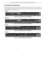
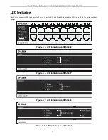
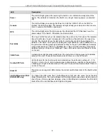
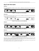
Summary of Contents for xStack DGS-3450

Page 1: ...xStack DGS 3400 Series Layer 2 Gigabit Ethernet Managed Switch Hardware Installation Guide Product Model xStack DGS 3400 Series Layer 2 Gigabit Fast Ethernet Managed Switch i ...

Page 2: ... Link Computer Corporation is strictly forbidden Trademarks used in this text D Link and the D LINK logo are trademarks of D Link Computer Corporation Microsoft and Windows are registered trademarks of Microsoft Corporation Other trademarks and trade names may be used in this document to refer to either the entities claiming the marks and names or their products D Link Computer Corporation disclai...

Page 3: ...lation 17 Package Contents 17 Installation Guidelines 17 Installing the Switch without the Rack 18 Installing the Switch in a Rack 18 Mounting the Switch in a Standard 19 Rack 19 Power On 19 Power Failure 19 Installing the SFP ports 20 The Optional Module 21 Installing the Module 22 External Redundant Power System 23 Connecting the Switch 25 Switch to End Node 25 Switch to Switch 25 Connecting To ...

Page 4: ...tion 34 Introduction 34 Logging in to the Web Manager 34 Web based User Interface 35 Areas of the User Interface 35 Web Pages 37 Appendix A 38 Technical Specifications 38 Appendix B 40 Cables and Connectors 40 Appendix C 41 Cable Lengths 41 Glossary 42 ...

Page 5: ...xample use the copy command Boldface Typewriter Font Indicates commands and responses to prompts that must be typed exactly as printed in the manual Initial capital letter Indicates a window name Names of keys on the keyboard have initial capitals For example Click Enter Italics Indicates a window name or a field Also can indicate a variables or parameter that is replaced with an appropriate word ...

Page 6: ...oduct in a wet environment If the system gets wet see the appropriate section in the troubleshooting guide or contact your trained service provider Do not push any objects into the openings of the system Doing so can cause fire or electric shock by shorting out interior components Use the product only with approved equipment Allow the product to cool before removing covers or touching internal com...

Page 7: ...even surfaces General Precautions for Rack Mountable Products Observe the following precautions for rack stability and safety Also refer to the rack installation documentation accompanying the system and the rack for specific caution statements and procedures Systems are considered to be components in a rack Thus component refers to any system as well as to various peripherals or supporting hardwa...

Page 8: ...the lithium battery of the Switch may cause the battery to explode Replace this battery only with the same or equivalent type recommended by the manufacturer Discard used batteries according to the manufacturer instructions Protecting Against Electrostatic Discharge Static electricity can harm delicate components inside the system To prevent static damage discharge static electricity from your bod...

Page 9: ...tion D Link s next generation xStack DGS 3400 Series switches are high port density stackable switches that combine the ultimate performance with fault tolerance security management functions with flexibility and ease of use All these features typically found in the more expensive chassis based solutions are available from the xStack DGS 3400 switch series at the price of a stackable switch All xS...

Page 10: ...CACS and RADIUS protocols Dual Image Firmware Simple Network Time Protocol support MAC Notification support System and Port Utilization support System Log Support High performance switching engine performs forwarding and filtering at full wire speed up to 128Gbps Full and half duplex for all gigabit ports Full duplex allows the switch port to simultaneously transmit and receive data It only works ...

Page 11: ... Gigabit ports Four Combo SFP Ports Two slots open for single port 10GE XFP or 10GBASE CX4 modules One RS 232 DB 9 console port DGS 3426P Twenty four PoE Compliant 10 100 1000BASE T Gigabit ports Four Combo SFP Ports Two slots open for single port 10GE XFP or 10GBASE CX4 modules One RS 232 DB 9 console port DGS 3427 Twenty four 10 100 1000BASE T Gigabit ports Four Combo SFP Ports Three slots open ...

Page 12: ...s and SFP port LEDs The front panel includes a seven segment LED indicating the Stack ID number A separate table below describes LED indicators in more detail DGS 3426P also includes a Mode Select button for changing the mode Link Act State to PoE DGS 3426 Figure 2 1 Front Panel View of the DGS 3426 DGS 3426P Figure 2 2 Front Panel View of the DGS 3426P DGS 3427 Figure 2 3 Front Panel View of the ...

Page 13: ...rs The Switch supports LED indicators for Power Console RPS and Port LEDs including 10GE port LEDs for optional module inserts Figure 2 5 LED Indicators on DGS 3450 Figure 2 6 LED Indicators on DGS 3427 Figure 2 7 LED Indicators on DGS 3426 Figure 2 8 LED Indicators on DGS 3426P ...

Page 14: ...rt while a blinking green light indicates activity on the port at 1000Mbps A steady orange light denotes a valid 10 or 100Mbps link on the port while a blinking orange light indicates activity on the port at 100Mbps These LEDs will remain dark if there is no link on the port 10GE Ports A steady green light denotes a valid link on the port while a blinking green light indicates activity on the port...

Page 15: ...nal module inserts Figure 2 11 Rear panel view of the DGS 3427 DGS 3450 The rear panel of the DGS 3450 contains an AC power connector two empty slots for optional module inserts a redundant power supply connector a RS 232 DCE console port for Switch management and a system fan vent Figure 2 12 Rear panel view of the DGS 3450 The AC power connector is a standard three pronged connector that support...

Page 16: ...east 6 inches of space at the rear and sides of the Switch for proper ventilation Be reminded that without proper heat dissipation and air circulation system components might overheat which could lead to system failure and severely damage components Figure 2 13 Side Panel view of the DGS 3450 Figure 2 14 Side Panel view of the DGS 3426 and DGS 3427 Figure 2 15 Side Panel view of the DGS 3426P ...

Page 17: ...delines Please follow these guidelines for setting up the Switch Install the Switch on a sturdy level surface that can support at least 6 6 lb 3 kg of weight Do not place heavy objects on the Switch The power outlet should be within 1 82 meters 6 feet of the Switch Visually inspect the power cord and see that it is fully secured to the AC power port Make sure that there is proper heat dissipation ...

Page 18: ...nough ventilation space between the Switch and any other objects in the vicinity Figure 2 16 Prepare Switch for installation on a desktop or shelf Installing the Switch in a Rack The Switch can be mounted in a standard 19 rack Use the following diagrams as a guide Figure 2 17 Fasten mounting brackets to Switch Fasten the mounting brackets to the Switch using the screws provided With the brackets a...

Page 19: ...the AC power cord into the power connector of the Switch and the other end into the local power source outlet 2 After powering on the Switch the LED indicators will momentarily blink This blinking of the LED indicators represents a reset of the system Power Failure As a precaution in the event of a power failure unplug the Switch When power is resumed plug the Switch back in ...

Page 20: ...bling in order to uplink various other networking devices for a gigabit link that may span great distances These SFP ports support full duplex transmissions have auto negotiation and can be used with DEM 310GT 1000BASE LX DEM 311GT 1000BASE SX DEM 314GT 1000BASE LH and DEM 315GT 1000BASE ZX transceivers See the figure below for installing the SFP ports in the Switch Figure 2 19 Inserting the fiber...

Page 21: ...nd therefore has a transmit length limit up to 1 meter Compliant with the IEEE802 3ak standard this module uses a 4 laned copper connector for data transfer in full duplex mode within a stacking configuration To install these modules in the DGS 3400 Series Switch follow the simple steps listed below CAUTION Before adding the optional module make sure to disconnect all power sources connected to th...

Page 22: ... reaches the back as shown in the following figure Gently but firmly push in on the module to secure it to the Switch The module should fit snugly into the corresponding receptors Figure 2 22 Inserting the optional module into the Switch DGS 3450 Now tighten the two screws at adjacent ends of the module into the available screw holes on the Switch The upgraded Switch is now ready for use Figure 2 ...

Page 23: ...al redundant power system The diagrams below illustrate a proper RPS power connection to the Switch Please consult the documentation for information on power cabling and connectors and setup procedure Figure 2 24 The DGS 3450 with the DPS 500 chassis RPS Figure 2 25 The DGS 3450 with the DPS 500 Redundant External Power Supply ...

Page 24: ...400 Switch Series the DGS 3426P utilizes the DPS 600 as its External Redundant Power Supply The DPS 600 is the ONLY RPS to be used with the DGS 3426P NOTE See the DPS 500 or DPS 600 documentation for more information CAUTION Do not use the Switch except DGS 3426P with any redundant power system other than the DPS 500 ...

Page 25: ... when the link is valid A blinking LED indicates packet activity on that port Switch to Switch There is a great deal of flexibility on how connections are made using the appropriate cabling Connect a 10BASE T hub or switch to the Switch via a twisted pair Category 3 4 or 5 UTP STP cable Connect a 100BASE TX hub or switch to the Switch via a twisted pair Category 5 UTP STP cable Connect 1000BASE T ...

Page 26: ...ing to a network backbone server or server farm The copper ports operate at a speed of 1000 100 or 10Mbps in full or half duplex mode The fiber optic ports can operate at 1000Mbps in full duplex mode only Connections to the Gigabit Ethernet ports are made using a fiber optic cable or Category 5e copper cable depending on the type of port A valid connection is indicated when the Link LED is lit Fig...

Page 27: ...onfigure the Switch monitor the LED panel and display statistics graphically using a web browser such as Netscape Navigator version 6 2 and higher or Microsoft Internet Explorer version 5 0 and higher 2 SNMP Based Management The Switch can be managed with an SNMP compatible console program The Switch supports SNMP version 1 0 version 2 0 and version 3 0 The SNMP agent decodes the incoming SNMP mes...

Page 28: ...2000 Service Pack 2 or later is installed Windows 2000 Service Pack 2 allows use of arrow keys in HyperTerminal s VT100 emulation See www microsoft com for information on Windows 2000 service packs After you have correctly set up the terminal plug the power cable into the power receptacle on the back of the Switch The boot sequence appears in the terminal After the boot sequence completes the cons...

Page 29: ...he Switch supports user based security that can allow prevention of unauthorized users from accessing the Switch or changing its settings This section tells how to log onto the Switch via out if band console connection NOTE The passwords used to access the Switch are case sensitive for example S is not the same as s NOTE Press Ctrl R to refresh the screen This command can be used at any time to fo...

Page 30: ...authorized access to the Switch and record the passwords for future reference To create an administrator level account for the Switch do the following 1 At the CLI login prompt enter create account admin followed by the user name and press the Enter key 2 The Switch will then prompt the user to provide a password Type the password used for the administrator account being created and press the Ente...

Page 31: ...trieve MIB objects private Allows authorized management stations to retrieve and modify MIB objects SNMP v 3 uses a more sophisticated authentication process that is separated into two parts The first part is to maintain a list of users and their attributes that are allowed to act as SNMP managers The second part describes what each user on that list can do as an SNMP manager The Switch allows gro...

Page 32: ...nabled TCP 23 WEB Enabled TCP 80 SNMP Disabled RMON Disabled CTRL C ESC q Quit SPACE n Next Page ENTER Next Entry a All Figure 4 4 show switch command The Switch s MAC address also appears in Switch Information menu of the web based management interface The IP address for the Switch must be set before using the Web based manager The Switch IP address can be automatically set using BOOTP or DHCP pr...

Page 33: ...the command was executed successfully The Switch can now be configured and managed via Telnet and the CLI or via the Web based management NOTE The DGS 3400 series of switches have the capability to be configured for an IP address of 0 0 0 0 or in essence have no IP address This function maybe used to disable Layer 3 functions of the Switch When the IP address is set to 0 0 0 0 invalid IP address t...

Page 34: ...he Switch using the HTTP protocol The Web based management module and the Console program and Telnet are different ways to access the same internal switching software and configure it Thus all settings encountered in web based management are the same as those found in the console program Logging in to the Web Manager To begin managing the Switch simply run the browser installed on your computer an...

Page 35: ...h management features available in the web based manager are explained below Web based User Interface The user interface provides access to various Switch configuration and management screens allows the user to view performance statistics and permits graphical monitoring of the system status Areas of the User Interface The figure below shows the user interface Three distinct areas divide the user ...

Page 36: ...splay menus Click the D Link logo to go to the D Link website Area 2 Presents a graphical near real time image of the front panel of the Switch This area displays the Switch s ports and expansion modules showing port activity duplex mode or flow control depending on the specified mode Some management functions including port configuration are accessible here Area 3 Presents switch information base...

Page 37: ... directories Bandwidth Control QoS Scheduling Mechanism QoS Output Scheduling 802 1p Default Priority and 802 1p User Priority ACL Contains the following menu pages and sub directories Time Range Access Profile Table ACL Flow Meter and CPU Interface Filtering Security Contains the following menu pages and sub directories Authorization Network State Settings Traffic Control Port Security IP MAC Por...

Page 38: ...ation Control IEEE 802 3x Full duplex Flow Control IEEE 802 1u Fast Ethernet IEEE 802 3af Power over Ethernet Protocols CSMA CD Data Transfer Rates Ethernet Fast Ethernet Gigabit Ethernet Fiber Optic Half duplex Full duplex 10 Mbps 20Mbps 100Mbps 200Mbps 1000Mbps 2000Mbps SFP Mini GBIC Support IEEE 802 3z 1000BASE LX DEM 310GT transceiver IEEE 802 3z 1000BASE SX DEM 311GT transceiver IEEE 802 3z 1...

Page 39: ...idity 5 95 non condensing Dimensions 441mm x 389mm x 44mm Weight DGS 3400 Series Switch DGS 3426 5 42 kg DGS 3426P 6 kg DGS 3427 5 51 kg DGS 3450 5 74 kg Module Inserts DEM 410CX 0 16 kg DEM 410X 0 18 kg EMI CE class A FCC Class A Safety CSA International CB Report Performance Transmission Method Store and forward Packet Buffer 0 75 MB per device Packet Filtering Forwarding Rate Full wire speed fo...

Page 40: ...The following diagrams and tables show the standard RJ 45 receptacle connector and their pin assignments Appendix 1 1 The standard RJ 45 port and connector RJ 45 Pin Assignments Contact MDI X Port MDI II Port 1 RD receive TD transmit 2 RD receive TD transmit 3 TD transmit RD receive 4 1000BASE T 1000BASE T 5 1000BASE T 1000BASE T 6 TD transmit RD receive 7 1000BASE T 1000BASE T 8 1000BASE T 1000BA...

Page 41: ... Media Type Maximum Distance Mini GBIC 1000BASE LX Single mode fiber module 1000BASE SX Multi mode fiber module 1000BASE LHX Single mode fiber module 1000BASE ZX Single mode fiber module 10km 550m 2km 40km 80km 1000BASE T Category 5e UTP Cable Category 5 UTP Cable 1000 Mbps 100m 100BASE TX Category 5 UTP Cable 100 Mbps 100m 10BASE T Category 3 UTP Cable 10 Mbps 100m ...

Page 42: ...tion devices on the network broadcast storm Multiple simultaneous broadcasts that typically absorb available network bandwidth and can cause network failure console port The port on the Switch accepting a terminal or modem connector It changes the parallel arrangement of data within computers to the serial form used on data transmission links This port is most often used for dedicated local manage...

Page 43: ...y designed to be used in managing TCP IP internets SNMP is presently implemented on a wide range of computers and networking equipment and may be used to manage many aspects of network and end station operation Spanning Tree Protocol STP A bridge based system for providing fault tolerance on networks STP works by allowing the user to implement parallel paths for network traffic and ensure that red...

Page 44: ...ation pertaining to the product and in that case the product is being sold As Is without any warranty whatsoever including without limitation the Warranty as described herein notwithstanding anything stated herein to the contrary Submitting A Claim The customer shall return the product to the original purchase point based on its return policy In case the return policy period has expired and the pr...

Page 45: ...ms Inc Other trademarks or registered trademarks are the property of their respective owners Copyright Statement No part of this publication or documentation accompanying this product may be reproduced in any form or by any means or used to make any derivative such as translation transformation or adaptation without permission from D Link Corporation D Link Systems Inc as stipulated by the United ...

Page 46: ...Registration Register your D Link product online at http support dlink com register Product registration is entirely voluntary and failure to complete or return this form will not diminish your warranty rights ...

Page 47: ... the defective Hardware the price paid by the original purchaser for the defective Hardware will be refunded by D Link upon return to D Link of the defective Hardware All Hardware or part thereof that is replaced by D Link or for which the purchase price is refunded shall become the property of D Link upon replacement or refund Limited Software Warranty D Link warrants that the software portion of...

Page 48: ... not to be defective or non conforming What Is Not Covered This limited warranty provided by D Link does not cover Products that have been subjected to abuse accident alteration modification tampering negligence misuse faulty installation lack of reasonable care repair or service in any way that is not contemplated in the documentation for the product or if the model or serial number has been alte...

Page 49: ...ir respective proprietors Copyright Statement No part of this publication may be reproduced in any form or by any means or used to make any derivative such as translation transformation or adaptation without permission from D Link Corporation D Link International Ptd Ltd FCC Warning This equipment has been tested and found to comply with the limits for a Class A digital device pursuant to Part 15 ...

Page 50: ...e warranty period on this product U S and Canadian customers can contact D Link technical support through our website or by phone Tech Support for customers within the United States D Link Technical Support over the Telephone USA 877 DLINK 55 877 354 6555 D Link Technical Support over the Internet http support dlink com Tech Support for customers within Canada D Link Technical Support over the Tel...

Page 51: ... uk ftp ftp dlink co uk Technische Unterstützung Deutschland Web http www dlink de E Mail support dlink de Telefon 49 0 1805 2787 0 14 pro Minute Zeiten Mo Fr 09 00 17 30 Uhr Österreich Web http www dlink at E Mail support dlink at Telefon 43 0 820 480084 0 116 pro Minute Zeiten Mo Fr 09 00 17 30 Uhr Schweiz Web http www dlink ch E Mail support dlink ch Telefon 41 0 848 331100 0 08 CHF pro Minute ...

Page 52: ...0 15ppm anytime Tech Support for customers within Belgium 070 66 06 40 www dlink be 0 175ppm peak 0 0875ppm off peak Tech Support for customers within Luxemburg 32 70 66 06 40 www dlink be Asistencia Técnica Asistencia Técnica Telefónica de D Link 34 902 30 45 45 0 067 min De Lunes a Viernes de 9 00 a 19 00 http www dlink es Supporto tecnico Supporto Tecnico dal lunedì al venerdì dalle ore 9 00 al...

Page 53: ... PO PÁ od 09 00 do 17 00 Pevna linka 1 78 CZK min mobil 5 40 CZK min Technikai Támogatás Tel 06 1 461 3001 Fax 06 1 461 3004 Land Line 14 99 HUG min Mobile 49 99 HUF min email support dlink hu URL http www dlink hu Teknisk Support D Link Teknisk telefon Support 820 00 755 Hverdager 08 00 20 00 D Link Teknisk Support over Internett http www dlink no Teknisk Support D Link teknisk support over telef...

Page 54: ...εφαλληνίας 64 11251 Αθήνα Τηλ 210 86 11 114 Δευτέρα Παρασκευή 09 00 17 00 Φαξ 210 8611114 http www dlink gr support Assistência Técnica Assistência Técnica da D Link na Internet http www dlink pt e mail soporte dlink es Teknisk Support D Link Teknisk Support via telefon 0900 100 77 00 Vardagar 08 00 20 00 D Link Teknisk Support via Internet http www dlink se ...

Page 55: ...k biz hr Tehnična podpora Zahvaljujemo se vam ker ste izbrali D Link proizvod Za vse nadaljnje informacije podporo ter navodila za uporabo prosimo obiščite D Link ovo spletno stran www dlink eu www dlink biz sl Suport tehnica Vă mulţumim pentru alegerea produselor D Link Pentru mai multe informaţii suport şi manuale ale produselor vă rugăm să vizitaţi site ul D Link www dlink eu www dlink ro ...

Page 56: ...ddress helpdesk dlink co in techsupport dlink co in Website www dlink co in Indonesia Malaysia Singapore and Thailand Tel 62 21 5731610 Indonesia Tel 1800 882 880 Malaysia Tel 65 6501 4200 Singapore Tel 66 2 719 8978 9 Thailand 24 7 for English Support Only http www dlink com sg support e mail support dlink com sg Korea Tel 82 2 2028 1815 Monday to Friday 9 00am to 6 00pm http www d link co kr e m...

Page 57: ... 92 21 4548158 or 92 21 4548310 Monday to Friday 10 00am to 6 00pm http support dlink me com E mail zkashif dlink me com South Africa and Sub Sahara Region Tel 27 12 661 2025 08600 DLINK for South Africa only Monday to Friday 8 30am to 9 00pm South Africa Time http www d link co za Turkey Tel 90 212 2895659 Monday to Friday 9 00am to 6 00pm http www dlink com tr e mail turkiye dlink me com e mail ...

Page 58: ...ink D Link предоставляет бесплатную поддержку для клиентов в течение гарантийного срока Клиенты могут обратиться в группу технической поддержки D Link по телефону или через Интернет Техническая поддержка D Link 7 495 744 00 99 Техническая поддержка через Интернет http www dlink ru e mail support dlink ru ...

Page 59: ...ombia 01800 9525465 Lunes a Viernes 06 00am a 19 00pm Costa Rica 0800 0521478 Lunes a Viernes 05 00am a 18 00pm Ecuador 1800 035465 Lunes a Viernes 06 00am a 19 00pm El Salvador 800 6335 Lunes a Viernes 05 00am a 18 00pm Guatemala 1800 8350255 Lunes a Viernes 05 00am a 18 00pm México 01800 1233201 Lunes a Viernes 06 00am a 19 00pm Panamá 011 008000525465 Lunes a Viernes 05 00am a 18 00pm Perú 0800...

Page 60: ...il A D Link fornece suporte técnico gratuito para clientes no Brasil durante o período de vigência da garantia deste produto Suporte Técnico para clientes no Brasil Telefone São Paulo 11 2185 9301 Segunda à sexta Das 8h30 às 18h30 Demais Regiões do Brasil 0800 70 24 104 E mail e mail suporte dlinkbrasil com br ...

Page 61: ...方式與D Link台灣 地區技術支援工程師聯絡 D Link 免付費技術諮詢專線 0800 002 615 服務時間 週一至週五 早上9 00到晚上9 00 不含周六 日及國定假日 網 站 http www dlink com tw 電子郵件 dssqa_service dlink com tw 如果您是台灣地區以外的用戶 請參考D Link網站全球各地 分公司的聯絡資訊以取得相關支援服務 產品保固期限 台灣區維修據點查詢 請參考以下網頁說明 http www dlink com tw 產品維修 使用者可直接送至全省聯強直營維修站或請洽您的原購買經銷商 ...

Page 62: ...okumentasi pengguna dapat diperoleh pada situs web D Link Dukungan Teknis untuk pelanggan Dukungan Teknis D Link melalui telepon Tel 62 21 5731610 Dukungan Teknis D Link melalui Internet Email support dlink co id Website http support dlink co id ...

Page 63: ...Technical Support この度は弊社製品をお買い上げいただき 誠にありがとうご ざいます 下記弊社 Web サイトからユーザ登録及び新製品登録を 行っていただくと ダウンロードサービスにて サポート情報 ファームウェア ユーザマニュアルを ダウンロードすることができます ディーリンクジャパン Web サイト URL http www dlink jp com ...

Page 64: ...技术支持 办公地址 北京市东城区北三环东路 36 号 环球贸易中心 B 座 26F 02 05 室 邮编 100013 技术支持中心电话 8008296688 028 66052968 技术支持中心传真 028 85176948 各地维修中心地址请登陆官方网站查询 网址 http www dlink com cn 办公时间 周一到周五 早09 00到晚18 00 ...

Page 65: ... site 1 employee 2 9 10 49 50 99 100 499 500 999 1000 or more 3 What network protocol s does your organization use XNS IPX TCP IP DECnet Others_____________________________ 4 What network operating system s does your organization use D Link LANsmart Novell NetWare NetWare Lite SCO Unix Xenix PC NFS 3Com 3 Open Cisco Network Banyan Vines DECnet Pathwork Windows NT Windows 98 Windows 2000 ME Windows...

Page 66: ......

Reviews: