background image

Power On (AC Power)

Plug one end of the AC power cord into the power socket of the Switch and the other end

into the local power source outlet. 

Power Failure (AC Power)

In   the   event   of   a   power   failure,   just   as   a   precaution,   unplug   the   power   cord   from   the
Switch. After the power returns, plug the power cord back into the power socket of the
Switch.

6

Connecting to Power

Connecting to a Redundant Power Supply

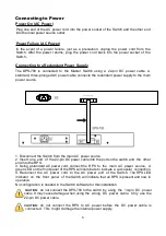
The DPS-700  is  connected  to  the  Master  Switch  using  a  22-pin  DC  power  cable.  A 
standard, three-pronged AC power cable connects the redundant power supply to the main 
power source.


CAUTION:

  do not connect the DPS-700 to the switch by  using  the  14-pin  DC  power  

CAUTION:

  do  not  connect  the  RPS  to  AC  power  before  the  DC  power  cable  is  

1. Disconnect the Switch from the main AC power source.
2. Insert  one  end  of  the 22-pin DC power cable into the port on the switch and  the  other 
end into the RPS.
3. Using a standard AC power cord, connect the  RPS  to  the  main  AC  power  source.  A 
green LED on the front panel of the RPS will illuminate to indicate a successful  connection.
4. Reconnect  the  AC  power  cord  to  the  AC  power  port  of  the  Switch.  The RPS LED 
indicator  on  the  front  panel  of  the Switch will indicate that an RPS is present and now in 
operation.
No configuration is needed in the Switch software for this installation.

cable. It may cause damage when using the  wrong  DC  power  cable.  Only  use  the 
22-pin DC power cable.

 connected.  This  might  damage the internal power supply.

Summary of Contents for xStack DGS-3620-52P

Page 1: ...0GE SFP ports L3 Stackable Managed Switch Управляемый L3 стекируемый коммутатор с 48 портами 10 100 1000Base T и 4 портами 10GBase X SFP 48 портов с PoE 802 3af at PoE бюджет 370 Вт 740 Вт с DPS 700 Quick Installation Guide Краткое руководство по установке ...

Page 2: ...roduction This Quick Installation Guide gives instructions for setting up the D Link DGS 3620 52P switch The model you have purchased may appear slightly different from those shown in the illustrations For more detailed information about the device its components making network connections and technical specifications please refer to the D Link website http www dlink com If any of the above items ...

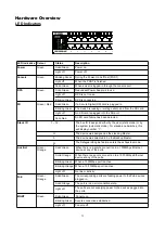
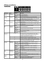
Page 3: ...vity Light off Console Green Blinking Green Solid Green When a user is logged in through the console port Solid Red When there is a secure connection to a 1000Mbps Ethernet device at any of the ports Light off When the POST is finished During the Power On Self Test POST 1 12 H The device was assigned as the stacking Master The device was selected to be the Backup Master The Safeguard Engine featur...

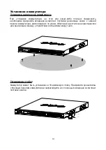
Page 4: ...e attached on the bottom at each corner of the device s base Allow enough ventilation space between the device and the objects around it Installing the Switch in a Standard 19 Rack The Switch can be mounted in a standard 19 1U rack using the provided mounting brackets Fasten the mounting brackets to the sides of the Switch using the screws provided 4 ...

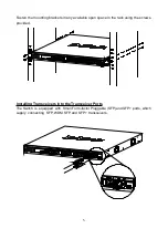
Page 5: ...ailable open space in the rack using the screws provided Installing Transceivers into the Transceiver Ports The Switch is equipped with Small Form factor Pluggable SFP and SFP ports which supply connecting SFP WDM SFP and SFP transceivers 5 ...

Page 6: ...y using the 14 pin DC power CAUTION do not connect the RPS to AC power before the DC power cable is 1 Disconnect the Switch from the main AC power source 2 Insert one end of the 22 pin DC power cable into the port on the switch and the other end into the RPS 3 Using a standard AC power cord connect the RPS to the main AC power source A green LED on the front panel of the RPS will illuminate to ind...

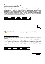
Page 7: ... the link is active A blinking LED indicates packet activity on that port NOTE all high performance N Way Ethernet ports can support both MDI II and Switch to Switch There is a great deal of flexibility on how connections are made using the appropriate cabling Connect a 10Base T switch port to the Switch via a twisted pair Category 3 4 or 5 UTP STP cable Connect a 100Base TX switch port to the Swi...

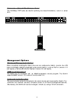
Page 8: ...wser such as FireFox version 3 0 and higher or Microsoft Internet Explorer version 5 0 and higher SNMP based Management The Switch can be managed with an SNMP compatible console program The Switch supports SNMP version 1 0 version 2 0 and version 3 0 Command Line Interface CLI The user can also connect a computer to the serial console port to access the Switch The command line interface provides c...

Page 9: ...ws keys are selected After you have correctly set up the terminal plug the power cord into the power receptacle on the back of the Switch The boot sequence appears in the terminal After the boot sequence completes the console login screen displays Connecting to the Switch for the First Time Upon initial connection to the Switch the login screen appears see example below DGS 3620 52P Gigabit Ethern...

Page 10: ...ss network_address state enable disable gateway ipaddr show out_band_ipif Management Out of Band Management Settings Logging onto the Web Manager To access the Web User Interface the user simply runs the standard web browser and enter the Switch s IP address into the address bar of the browser and press the Enter key To access the Web UI from normal LAN ports the user needs to configure an IP addr...

Page 11: ... указанным в технических характеристиках устройства Не вскрывайте корпус устройства Перед очисткой устройства от загрязнений и пыли отключите питание устройства Удаляйте пыль с помощью влажной салфетки Не используйте жидкие аэрозольные очистители или магнитные статические устройства для очистки Избегайте попадания влаги в устройство Устройство должно также быть заземлено если это предусмотрено кон...

Page 12: ...нштейна для установки в 19 дюймовую стойку Комплект для монтажа 4 резиновые ножки Краткое руководство по установке 12 Введение В данном кратком руководстве по установке даны инструкции по настройке коммутатора DGS 3620 52P Приобретенная модель может незначительно отличаться от показанной на иллюстрациях Более подробную информацию об устройстве его компонентах настройке подключения к сети и техниче...

Page 13: ...у из портов подключено устройство скорость соединения 1000 Мбит с Выполняется процедура Power On Self Test POST Не горит Stack ID 1 12 H Идентификатор стека Stacking ID может быть задан пользователем вручную static mode или автоматически назначен системой automatic mode Автономные коммутаторы обозначаются цифрой 1 Резервный источник питания подключен осуществляется подача питания Коммутатор являет...

Page 14: ...ект поставки резиновые ножки к нижней панели коммутатора расположив их по углам Обеспечьте достаточное пространство для вентиляции между устройством и объектами вокруг него Установка в стойку Коммутатор может быть установлен в 19 дюймовую стойку Прикрепите кронштейны к боковым панелям коммутатора и зафиксируйте их с помощью входящих в комплект поставки винтов 14 ...

Page 15: ... коммутатор в стойку и закрепите его с помощью винтов входящих в комплект поставки 15 Подключение трансиверов Установите трансиверы в соответствующие порты коммутатора Поддерживаются трансиверы SFP WDM SFP и SFP ...

Page 16: ...ного кабеля питания подключите DPS 700 к основному источнику питания переменного тока Зеленый индикатор на передней панели DPS 700 будет означать что подключение успешно выполнено 4 Подключите коммутатор к источнику питания переменного тока Горящий индикатор на передней панели коммутатора будет означать что резервный источник питания успешно функционирует Программная настройка коммутатора при данн...

Page 17: ...анжевым Мигающий индикатор указывает на передачу или прием даннх на порту Стекирование коммутаторов В зависимости от порта подключение может быть выполнено при помощи следующих кабелей 17 Подключение конечных узлов ПРИМЕЧАНИЕ все высокопроизводительные N Way Ethernet порты поддерживают подключения MDI II и MDI X Порты 10Base T подключаются к коммутатору при помощи кабелей UTP STP Cat 3 4 или 5 Пор...

Page 18: ...спользовать Telnet SNMP менеджер Для управления коммутатором можно использовать любую консольную программу совместимую с SNMP Устройство поддерживает протокол SNMP версий 1 0 2 0 и 3 0 Web интерфейс Пользовательский интерфейс обеспечивает доступ к различным функциям настройки и управления позволяет пользователю следить за состоянием устройства с помощью панели индикаторов а также просматривать ста...

Page 19: ...трелок выберите клавиши терминала Убедитесь что не выбран режим клавиш Windows После успешной установки терминала подключите кабель питания к разъему на задней панели коммутатора На терминале отобразится процесс загрузки После завершения загрузки появится окно входа в консоль Первоначальное подключение к коммутатору DGS 3620 52P Gigabit Ethernet Switch Command Line Interface Firmware Build 2 60 01...

Page 20: ...ра статуса и IP адреса MGMT порта show out_band_ipif Настройка MGMT порта через Web интерфейс выполняется в разделе Management Out of Band Management Settings Авторизация через Web интерфейс Для входа в интерфейс введите адрес коммутатора в адресной строке браузера и нажмите Enter Для подключения к портам необходимо настроить адрес следующим образом Компьютеру должен быть назначен IP адрес из того...

Page 21: ...В 441 x 380 x 44 мм Условия эксплуатации Питание 100 240 В переменного тока 50 60 Гц внутренний универсальный источник питания с активной системой PFC Макс потребляемая мощность 517 1 Вт при загрузке 370 Вт PoE Тепловыделение 1763 31 БТЕ час при загрузке 370 Вт PoE MTBF часы 225645 Уровень шума При высокой скорости вентилятора 56 2 дБ При низкой скорости вентилятора 41 0 дБ Система вентиляции Smar...

Page 22: ...22 ...

Reviews: