9
4). Data Box (Junction box)
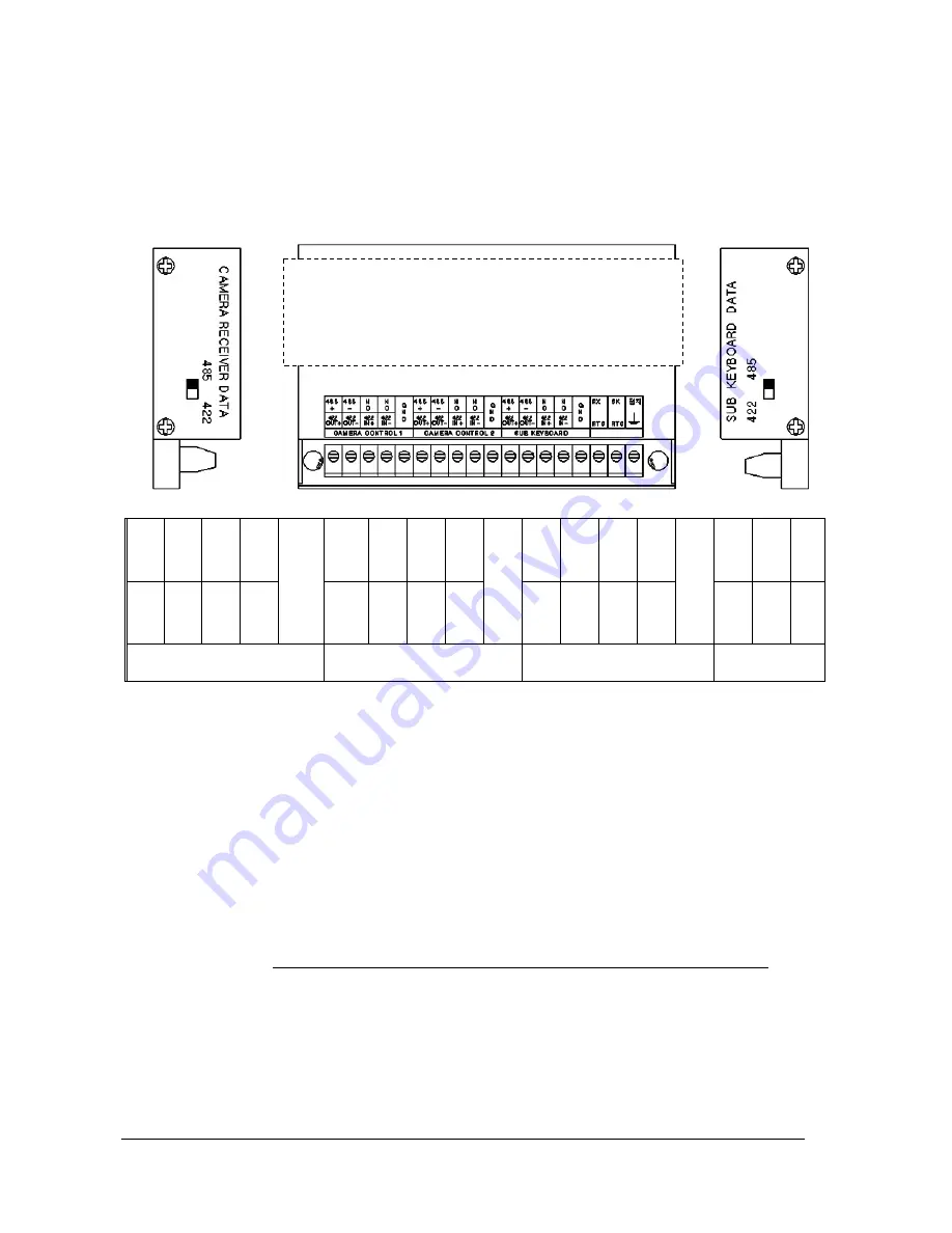
Set the communication mode to either RS-485 or RS-422 at your option.
INPUT/OUTPUT TERMINAL OF DATA JUNCTION BOX
Camera controls 1: This is the terminal that you can connect with up to 128 speed dome
cameras or receivers.
(Choose either 485 or 422 communication mode and connect in parallel)
Camera controls 2: this is the terminal that you can connect with up to 128 speed dome
cameras or receivers.
(Choose either 485 or 422 communication mode and connect in parallel)
(All together, 256 cameras can be controlled as above connection)
Sub keyboard: This is the terminal that you can connect sub-keyboard with when hoping to
use sub-keyboard and it does duplex transmission.
(Parallel connection is available when using RS485, but if you use RS422 only
1:1 connection is available.)
485+ 485- NC NC
GND
485+ 485- N C N C
GND
485+ 485- N C N C
GND
RX
RTS
RX
RTS
접지
422
OUT
422
OUT-
422
IN+
422
IN-
422
OUT+
422
OUT-
422
IN+
422
IN-
422
OUT
422
OUT-
422
IN+
422
IN-
CAMERA CONTROL 1
CAMERA CONTROL 2
SUB KEYBOARD
When communicating in RS-485, the switch(485/422)
at both sides should be moved to RS-485.
(It is set to RS-485 when we take from warehouse)
Summary of Contents for DCK-500B
Page 1: ...DCK 500B USER MANUAL CONTROL KEYBOARD ...
Page 39: ...39 5 Dimensions Junction Box ...
Page 41: ...41 3 When connected DVR with Matrix System DMX 25632 and PTZ Camera by DATA interface ...
Page 42: ...42 4 When connected DVR with Matrix System DMX 25632 and PTZ Camera by VIDEO interface ...
Page 47: ...47 ...


