6.3 Installation foundation
a. The unit should be located on the level foundation, the
ground floor or the roof which can bear operating weight of the
unit and the weight of maintenance personnel. Refer to Table
12-1 (Table of applicable models and parameters) for operating
weight.
b. If the unit is located so high that it is inconvenient for
maintenance personnel to conduct maintenance, the suitable
scaffold can be provided around the unit.
c. The scaffold must be able to bear the weight of maintenance
personnel and maintenance facilities.
d. The bottom frame of the unit is not allowed to be embedded
into the concrete of installation foundation.
e. A drainage ditch should be provided to allow drainage of
condensate that may form on the heat exchangers when the
units are running in heating mode. The drainage should ensure
that condensate is directed away from roadways and
footpaths, especially in locations where the climate is such that
condensate may freeze.
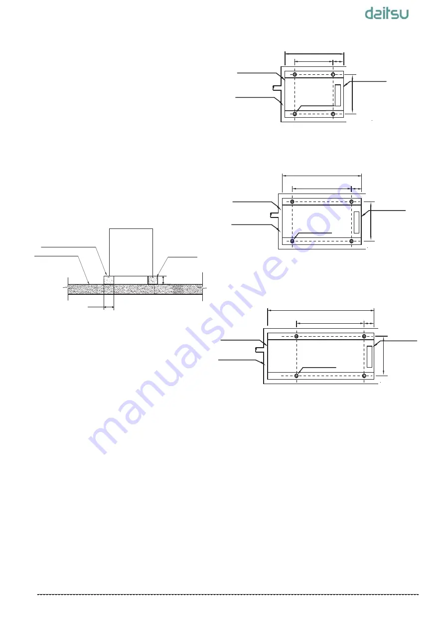
Top view of schematic diagram of installation
dimension of
CSAD UiAWP 100 PS
Fig. 6-7
1870
Drainage channel
Anchor bolt
800
926
Top view of schematic diagram of installation
dimension of
CSAD UiAWP 200 PS
Fig. 6-8
2200
Drainage channel
Anchor bolt
1105
958
Top view of schematic diagram of installation
dimension of
CSAD UiAWP 300 PS
Fig. 6-9
3220
Anchor bolt
2116
1008
180
530
425
Electric control
inlet and outlet
box side
pipe side
inlet and outlet
pipe side
inlet and outlet
pipe side
Drainage channel
Electric control
box side
Electric control
box side
≥80mm
Fig.6-6 Front view of base structure
Concrete base
h
≥
200mm
Rubber anti-vibration pads
Solid ground / surface
≥
200mm
a. A solid base prevents excess vibration and noise. Outdoor unit
bases should be constructed on solid ground or on structures of
sufficient strength to support the units’ weight.
b. Bases should be at least 200mm high to provide sufficient
access for installation of piping.Snow protection should also be
considered for the base height
.
c. Either steel or concrete bases may be suitable.
d. A typical concrete base design is shown in Fig. 6-6. A typical
concrete specification is 1 part cement, 2 parts sand and 4 parts
crushed stone with steel reinforcing bar. The edges of the base
should be chamfered.
e. To ensure that all contact points are equally secure, bases
should be completely level. Base design should ensure that the
points on the units’ bases designed for weight-bearing support are
fully supported.
Outdoor unit base structure design should take account of the
following considerations:
6.3.1 Base structure
Outdoor unit
6.3.2 Location drawing of installation foundation
of the unit
(unit: mm)
(unit: mm)
(unit: mm)
7
Installation Manual___________________________________________________________________________________
Summary of Contents for CSAD UiAWP 100 PS Series
Page 56: ...dcitsu...


