EE PRO for TI -89, 92 Plus
Equations - RL and RC Circuits
40
21.1 RL Natural Response
These four equations define all the key properties for the natural response
of an RL circuit with no energy sources. The first equation shows the
characteristic time constant
τ
in terms of the resistance R and the inductance
L. The second equation computes the decay of the voltage vL across the
inductor with an initial current I0. The third equation displays the decay of
the inductor current iL. The final equation expresses the energy dissipation
characteristic W of the circuit for the specified conditions.
τ =
L
R
Eq. 21.1.1
vL
I
R e
t
=
⋅ ⋅
−
0
τ
Eq. 21.1.2
iL
I
e
t
=
⋅
−
0
τ
Eq. 21.1.3
W
L I
e
t
= ⋅ ⋅
⋅ −
F
HG
I
KJ
− ⋅
1
2
0
1
2
2
τ
Eq. 21.1.4
Example 21.1
An RL circuit consists of a 400_mH inductor and a 125_
Ω
resistor. With an initial current of
100_mA, find the inductor current and voltage across the inductor 1_ms and 10_ms after the switch has been closed.
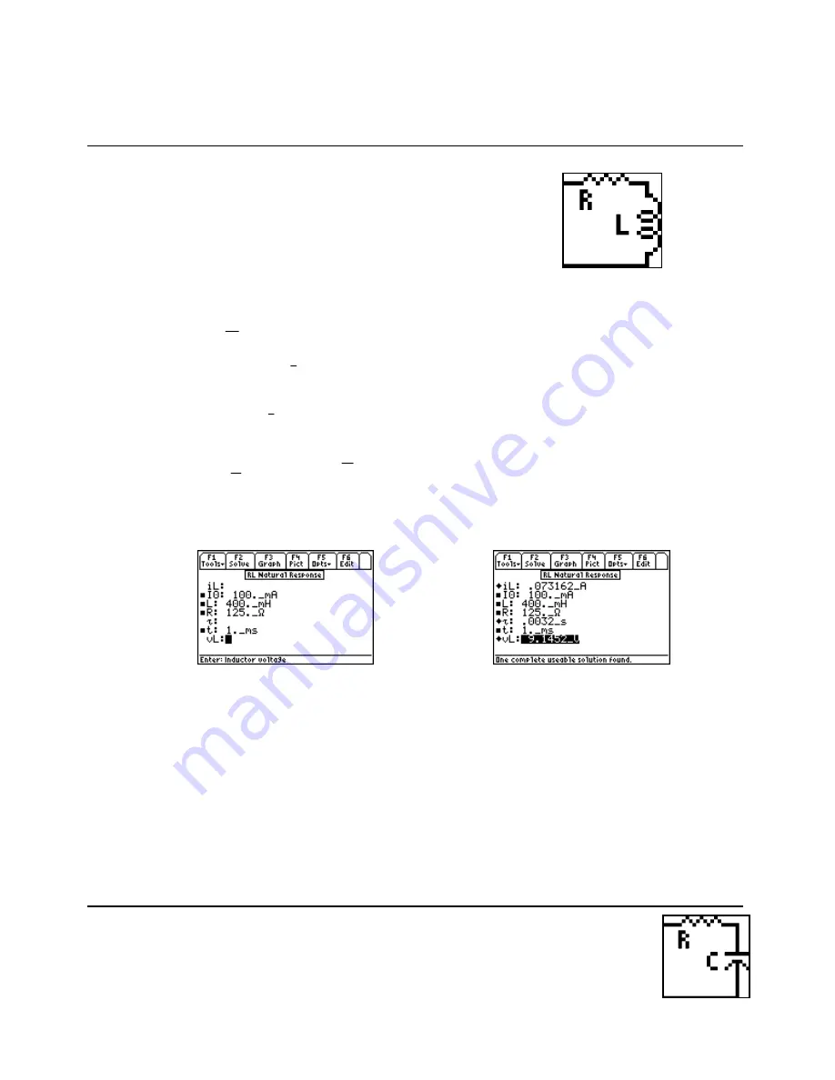
Entered Values
Calculated Results (1 ms)
Solution -
Upon examining the problem, the first three equations are needed to solve the problem.
Select these equations using the highlight bar and pressing
¸
, press
„
to display the input screen,
enter all the known variables and press
„
to solve. Perform the computations for a time of 1_ms, write
down all the results, enter 10 ms for t and press
„
to recalculate the results for the new time entry.
-PQYP8CTKCDNGU
+
AO#
.
AO*
4
A
Ω
V
AOUAOU
%QORWVGF4GUWNVU
K.
A#
X.
A8CHVGTAOU
K.
AO#
X.
A8CHVGTAOU
21.2 RC Natural Response
These four equations define the natural response of an RC circuit with no energy sources.
The first equation specifies the characteristic time constant
τ
in terms of the resistance R and the


