EE Pro for TI - 89, 92 Plus
Equations - OpAmp Circuits
70
26.2 Non-Inverting Amplifier
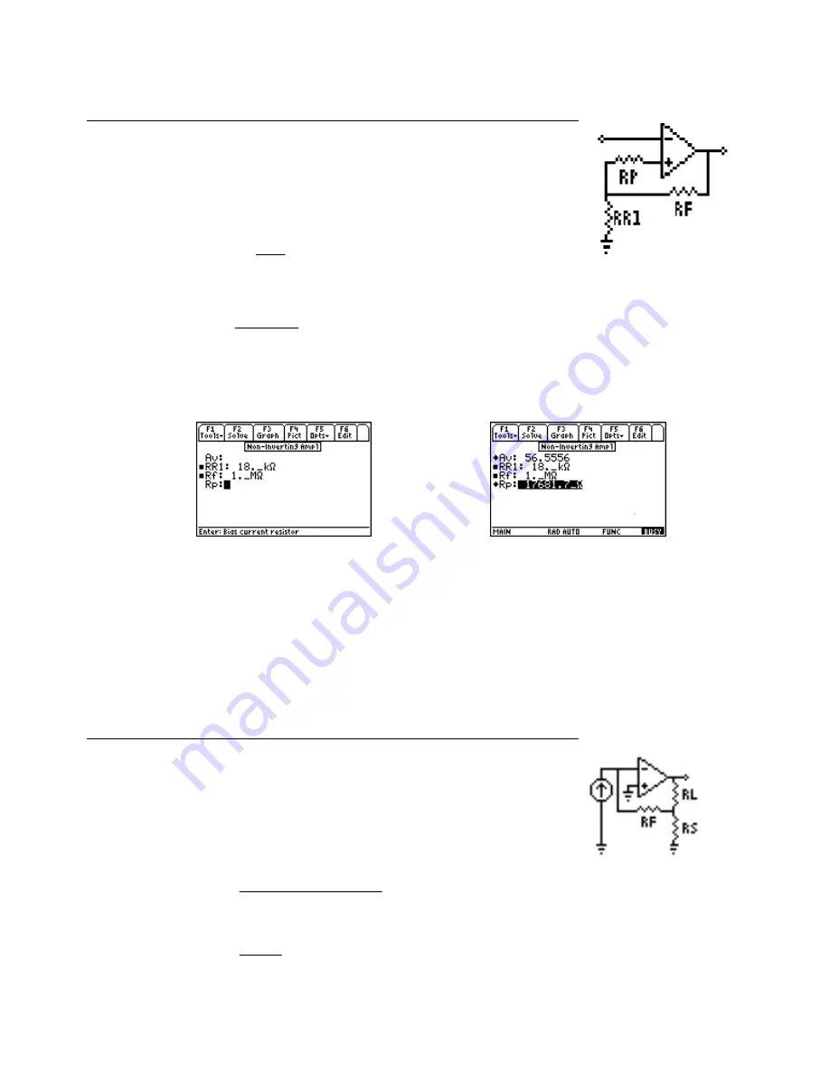
These equations define the properties of a non-inverting amplifier. The first equation
expresses the voltage gain Av in terms of the feedback resistor Rf and resistor RR1.
The second equation gives the value of Rp needed in the input circuit to minimize
offset current effects.
Av
Rf
RR
= +
1
1
Eq.
26.2.1
Rp
RR
Rf
RR
Rf
=
⋅
+
1
1
Eq. 26.2.2
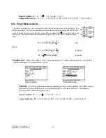
Example 26.2 -
Find the DC gain of a non-inverting amplifier with a feedback resistance of 1 M
Ω
and a
resistance to the load of 18 k
Ω
. Find the gain and the optimum value for a bias resistor.
Entered Values
Calculated Results
Solution -
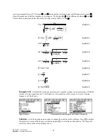
Use the first and second equations to compute the solution for this problem. Select these by
highlighting each equation and pressing the
¸
key. Press
„
to display the input screen, enter all the known
variables and press
„
to solve the equation. The computed results are shown in the screen displays above.
-PQYP8CTKCDNGU4H
A/
Ω
44
AM
Ω
%QORWVGF4GUWNVU
#X
4R
A
Ω
26.3 Current Amplifier
This section describes the properties of a current amplifier. The first equation shows
the relationship between the current gain Aic with feedback resistance Rf, load
resistance Rl, output resistance of OpAmp Ro, voltage divide resistor Rs, and voltage
gain Av. The remaining equations define the input resistance Rin and output resistance
Rout of the system.
Aic
Rs
Rf
Av
Rl
Ro
Rs
Av
=
+
⋅
+
+
⋅ +
b
g
b
g
1
Eq. 26.3.1
Rin
Rf
Av
=
+
1
Eq. 26.3.2


