EE PRO for TI - 89, 92 Plus
Equations - Linear Amplifiers
105
28.3 BJT (Common Collector)
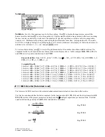
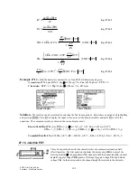
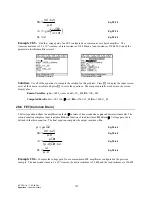
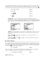
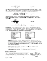
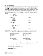
These six equations describe the properties of a transistor amplifier connected in a common collector configuration
at mid frequencies. The first equation couples the common emitter current gain
α
0 with the common base current
gain
β
0. The second equation computes the input impedance Rin in terms of base resistance rb, emitter resistance
re,
β
0, and load resistance Rl. Ro represents the output resistance in terms of the source resistance, common base
current gain
β
0 and the load resistance Rl. The current gain Ai is shown in the fourth equation in terms of the
collector resistance rrc,
α
0, re, and Rl. The final two equations cover the voltage gain Av and overall voltage gain
Aov for the amplifier system. Aov includes the effect of source impedance Rs.
β
α
α
0
0
1
0
=
−
Eq. 28.3.1
Rin
rb
re
Rl
=
+
⋅ +
+ ⋅
β
β
0
0 1
b
g
Eq. 28.3.2
Ro
re
Rs rb
= +
+
b
g
β
0
Eq. 28.3.3
Ai
rrc
rrc
Rl
re
=
⋅ −
+
+
1
0
α
b
g
Eq. 28.3.4
Av
Rl
re
Rl
=
⋅
+
α
0
Eq. 28.3.5
Aov
Rl
Rs
Rin
Rl
=
+ ⋅
+
+
+ ⋅
β
β
0 1
0 1
b
g
b
g
Eq. 28.3.6
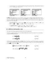
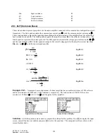
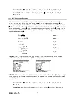
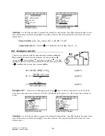
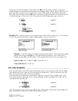
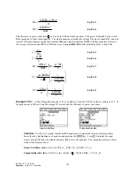
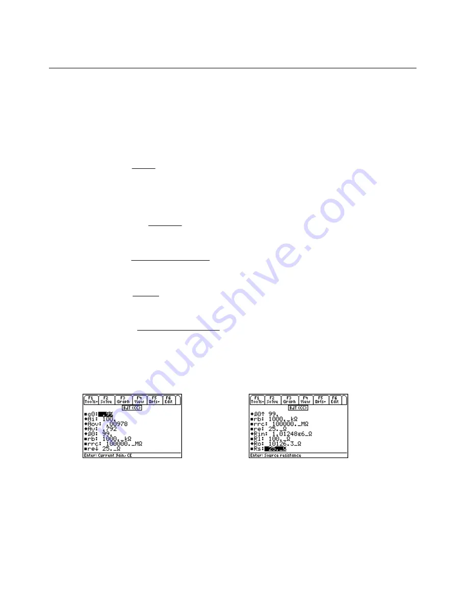
Example 28.3 -
An amplifier in a common collector configuration has a gain
α
0 of 0.99. The emitter, base and
collector resistances are 25
Ω
, 1000 k
Ω
, and 100,000 M
Ω
respectively. If the source resistance is 25
Ω
find all the
mid-band characteristics.
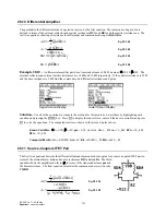
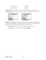
Upper Screen Display
Lower Screen Display
Solution -
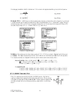
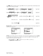
Use all of the equations to compute the solution for this problem. Press
„
to display the input screen,
enter all the known variables and press
„
to solve the equations. The computed results are shown in the screen
displays above.
-PQYP8CTKCDNGU
α
TD
AM
Ω
TTE
A/
Ω
TG
A
Ω
4N
A
Ω
4U
A
Ω
%QORWVGF4GUWNVU
#K
#QX
#X
β
4KP
'A
Ω
4Q
A
Ω


