EE PRO for TI - 89, 92 Plus
Equations - Class A, B, C Amplifiers
115
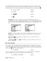
The compliance PP is defined as the full voltage swing across the emitter and collector and is expressed in terms of
the minimum and maximum transformer ratings VCEmx and VCEmn. VPP represents the peak to peak voltage in
the secondary transformer. The final two equations compute the output power Po and the conversion efficiency
ζ
.
PP
VCEmx VCEmn
=
−
Eq. 29.1.5
VPP
n PP
= ⋅
Eq. 29.1.6
Po
IC
R
=
⋅
∆
2
8
Eq. 29.1.7
ζ =
Po
Pdc
Eq. 29.1.8
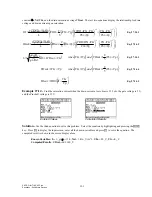
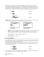
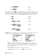
Example 29.1 -
A Class A power amplifier is coupled to a 50
Ω
load through the output of a
transformer with a turn ratio of 2. The quiescent operating current is 60 mA, and the incremental collector
current is 50 mA. The collector-to-admitter voltage swings from 6 V to 12 V. The supply collector voltage
is 15 V. Find the power delivered and the efficiency of power conversion. The maximum current is 110
mA.
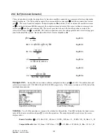
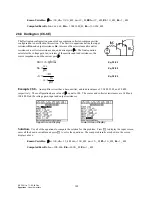
Upper Display
Lower Display
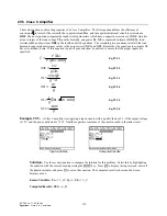
Solution -
Use all of the equations to solve this problem. Press
„
to display the input screen, enter all
the known variables and press
„
to solve the equation. The computed results are shown in the screen
displays above.
-PQYP8CTKCDNGU
∆
+%
O#
+%3
AO#
+OCZ
AO#
P
4N
Ω
8%%
A8
8%'OZ
A8
8%'OP
A8
%QORWVGF4GUWNVU
∆
8%'
A8
ζ
2FE
A9
2Q
A9
22
A8
4
A
Ω
4N
A
Ω
822
A8
29.2 Power Transistor
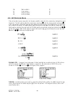
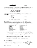
Power amplifiers generate heat needing rapid transfer to ambient surroundings. The six equations in this section
focus on thermal problems in terms of the junction temperature TJ, transistor currents IB and IC, and the instability
factor S. The first equation defines the junction temperature TJ as linearly related to the power dissipation Pd and
thermal resistance
θθ
JA and TA, the ambient temperature.
TJ
TA
JA Pd
=
+
⋅
θ
Eq. 29.2.1
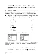
The next two equations focus on the collector current IC and base current IB in terms of the current gain hFE,
leakage current ICBO, external emitter resistance Rxt and external base resistance RB.
IC
hFE IB
hFE
ICBO
=
⋅ + +
⋅
1
b
g
Eq. 29.2.2

