EE PRO for TI - 89, 92 Plus
Equations - Class A, B, C Amplifiers
119
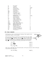
29.5 Class C Amplifier
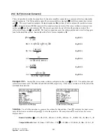
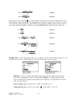
These six equations outline the properties of a Class C amplifier. The first equation defines the efficiency of
conversion
ζ
in terms of the current I, the coupled-in load Rrc, and the equivalent internal circuit loss resistance
RR0. The next equation computes the tuned circuit parameters which have a capacitive reactance of XXC, which is
given in terms of the load voltage V0, quality factor Q, and power Po. XL is expressed in terms of XXC,Q, load
resistance Rl, and resistance RR2 in the fourth and sixth equations. The remaining two equations calculate the load
harmonic suppression resistance values in the output circuit XC1 and XC2. Remember the equations to compute XL
have two distinct forms. If this equation is part of your selection, be advised to ensure that the proper inputs are
specified.
ζ =
⋅
⋅
+
I
Rrc
I
Rrc
RR
2
2
0
b
g
Eq. 29.5.1
XXC
V
Q Po
=
⋅
0
2
Eq. 29.5.2
XL
XXC Q
Q
=
⋅
+
2
2
1
Eq. 29.5.3
XC
Rl
Q
1
= −
Eq. 29.5.4
XL
Q
Rl
Rl
RR
= ⋅
+
+
1
2
d
i
Eq. 29.5.5
XC
RR
Q
2
2
= −
Eq. 29.5.6
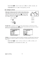
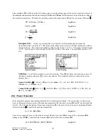
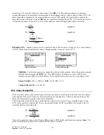
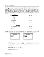
Example 29.5 -
A Class C amplifier is supplying a tuned circuit, with a quality factor of 5. If the output voltage
is 15 V and the power delivered is 75_W, find the capacitive reactance of the circuit needed in the tank circuit.
Input variables
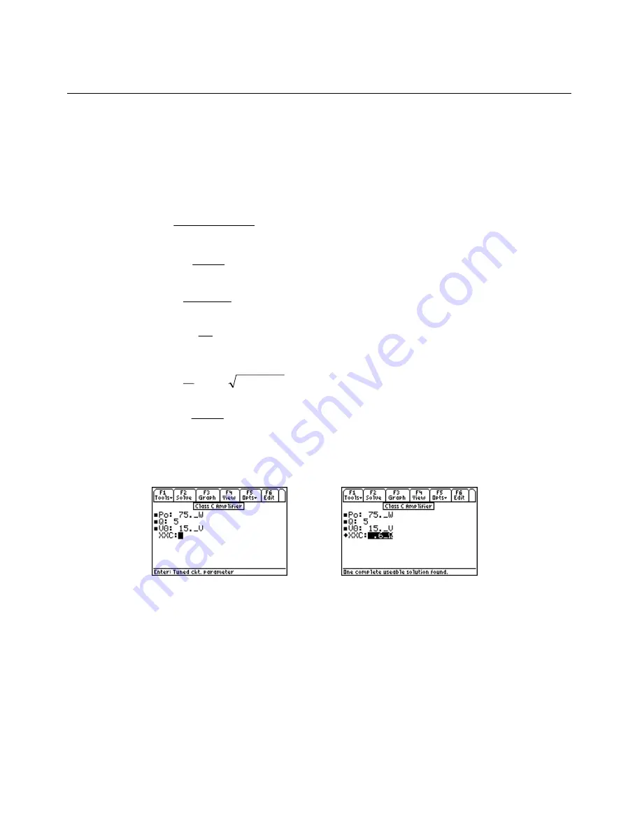
Computed results
Solution -
Use the second equation to compute the solution for this problem. Select this by highlighting
the equation with the cursor bar and pressing the
¸
key. Press
„
to display the input screen, enter all
the known variables and press
„
to solve the equation. The computed result is shown in the screen
displays above.
-PQYP8CTKCDNGU2Q
A9
3
8
A8
%QORWVGF4GUWNVU::%
A
Ω

