EE Pro for TI-89, 92 Plus
Equations - Motors and Generators
133
Solution
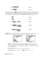
- Use the fourth equation to solve this problem. Select the equation with the cursor bar and
press
¸
. Press
„
to display the input screen, enter all the known variables and press
„
to solve the
selected equation. The computed result is shown in the screen display above.
-PQYP8CTKCDNGU -
φ
A9D
ω
O
ATU
%QORWVGF4GUWNV 'C
A8
31.8 DC Series Motor
These eight equations describe the performance characteristics of a series DC motor. The first equation links the
terminal voltage Vt to the back emf (Ea defined by the third equation) and the IR drop through the armature due to
armature resistance Ra, adjustable resistance Rd, and series resistance Rs. The second equation calculates the load
torque TL with the machine constant K, flux
φ
, load current IL, and the torque loss Tloss.
Vt K m Ra
Rs
Rd
IL
= ⋅ ⋅
+
+
+
⋅
φ ω
b
g
Eq. 31.8.1
TL K IL
Tloss
= ⋅ ⋅ −
φ
Eq. 31.8.2
The third equation defines the back emf in the armature Ea in terms of K,
φ
, and mechanical frequency
ω
m. The
fourth equation shows torque generated at the rotor due the magnetic flux
φ
and current IL.
Ea K m
= ⋅
⋅
ω φ
Eq. 31.8.3
T
K
IL
= ⋅ ⋅
φ
Eq. 31.8.4
The next equation shows a reciprocal quadratic link between
ω
m, Vt, K,
φ
, Ra, Rs, Rd, and torque T.
ω
φ
φ
m
Vt
K
Ra
Rs
Rd T
K
=
⋅
−
+
+
⋅
⋅
b
g
b
g
2
Eq. 31.8.5
The sixth equation computes the torque generated T as the sum of load torque TL and lost torque Tloss. The last
two equations show the connection between K,
φ
, a field constant Kf, load current IL, and torque T.
T Tloss TL
=
+
Eq. 31.8.6
K
Kf IL
⋅ =
⋅
φ
Eq. 31.8.7
T
Kf IL
=
⋅
2
Eq. 31.8.8
Example
31.8
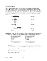
- A series motor, with a machine constant of 2.4, rotating at 62 rad/s, is supplied with a terminal
voltage of 110 V and produces a torque of 3 Nm. The armature resistance is 10
Ω
, the series resistance is 5
Ω
, and
the adjustable resistance is 0.001
Ω
. Find the average voltage induced in the armature, the flux, and the load
current.


