EE Pro for TI-89, 92 Plus
Equations - Motors and Generators
134
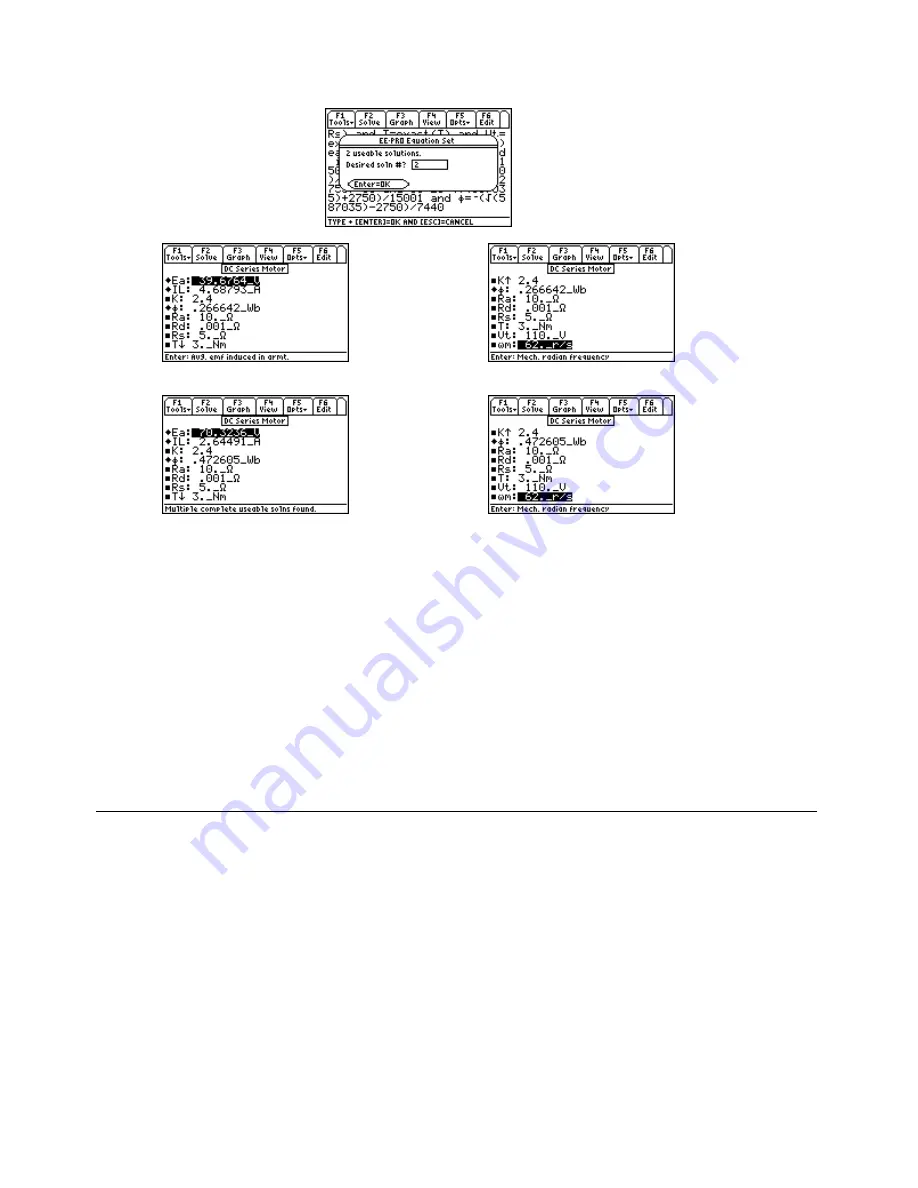
Solution 1: Upper Display
Solution 1: Lower Display
Solution 2: Upper Display
Solution 2: Lower Display
Solution
- The first, third and fifth equations are needed to compute a solution. Select these by
highlighting and pressing
¸
. Press
„
to display the input screen, enter all the known variables and
press
„
to solve the selected equation set. There are two possible solutions for this example. Type the
number of the solution set to be viewed and press
¸
twice. To view another solution set, press
„
to
and select another number. The computed results are shown in the screen displays above.
-PQYP8CTKCDNGU
-
4C
Ω
4F
A
Ω
4U
A
Ω
6
A0O
8V
A8
ω
ω
O
ATU
%QORWVGF4GUWNVU
'C
A8A8
+.
A#A#
φφ
A9DA9D
31.9 Permanent Magnet Motor
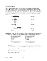
These five equations characterize the basic features of a permanent magnet motor. The first equation shows the back
emf Ea in terms of machine constant K, flux
φφ
, and radian velocity
ω
ω
m. The second equation shows the connection
between generated torque T, K,
φφ
and armature current Ia. The terminal voltage Vt is the sum of back emf Ea and
the inductive-resistance drop in the armature. The fourth equation shows conservation of various torques T, TL and
Tloss. The final equation displays the quadratic relationship of
ω
ω
m in terms of K, Vt,
φφ
, T and Ra.
Ea
K
m
= ⋅ ⋅
φ ω
Eq. 31.9.1
T
K
Ia
= ⋅ ⋅
φ
Eq. 31.9.2
Vt
Ea
Ra Ia
=
+
⋅
Eq. 31.9.3
T
Tloss TL
=
+
Eq. 31.9.4


