EE Pro for TI-89, 92 Plus
Equations - Motors and Generators
137
Pma
Rr
s
Ir
=
⋅
2
Eq. 31.11.1
The second equation shows the expression for torque T in terms of poles p, Pma and radian frequency of the
induced voltage in the stator
ω
ω
s. The third equation is an alternate representation of torque in terms of the applied
voltage Va, stator resistance Rst, Rr, inductive reactance XL, and
ω
ω
s.
T
p
Pma
s
= ⋅ ⋅
3
2
ω
Eq. 31.11.2
T
p
s
Rr
s
Va
Rst
Rr
s
XL
= ⋅
⋅
⋅
+
F
HG
I
KJ
+
3
2
2
2
2
ω
Eq. 31.11.3
The equation for Tmmax represents the maximum positive torque available at the rotor, given the parameters of the
induction motor stator resistance Rst, XL, Va, p, and
ω
ω
s.
Tm
p
s
Va
Rst
XL
Rst
max
= ⋅
⋅
+
+
3
4
2
2
2
ω
Eq. 31.11.4
The maximum slip sm in the fifth equation represents the condition when dT/ds=0.
sm
Rr
Rs
XL
=
+
2
2
Eq. 31.11.5
The sixth equation defines the so-called breakdown torque Tgmax of the motor. The final equation relates Rr with
machine constant KM and the rotor resistance per phase RR1.
Tg
p
s
Va
Rs
XL
Rst
max
= − ⋅
⋅
+
−
3
4
2
2
2
ω
Eq. 31.11.6
Rr
RR
KM
=
1
2
Eq. 31.11.7
Example
31.11
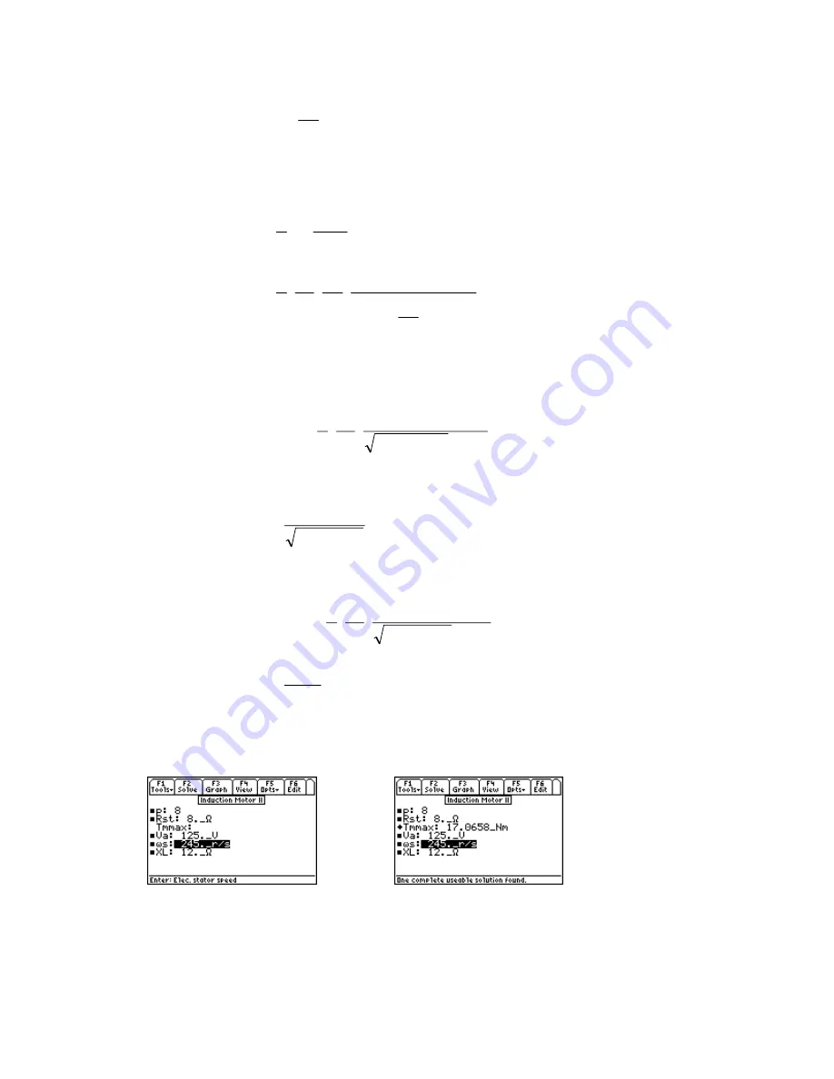
– An applied voltage of 125 V is applied to an eight pole motor rotating at 245 rad/s . The stator
resistance and reactance is 8 and 12
Ω
respectively. Find the maximum torque.
Entered Values
Calculated Results
Solution
- Use the fourth equation to compute the solution. Select by moving the cursor bar,
highlighting, and pressing
¸
. Press
„
to display the input screen, enter all the known variables and
press
„
to solve the equation.


