EE Pro for TI - 89, 92 Plus
Equations - Capacitors & Electric Fields
17
17.4 Parallel Plates
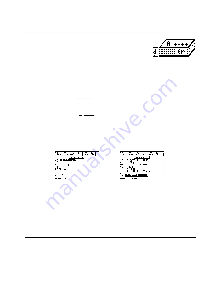
The five equations listed in this topic describe the electrical and mechanical forces
in a parallel plate capacitor. Two plates are separated by a distance
d
which is
small compared to the lateral dimensions so fringing field effects can be ignored.
The first equation computes the electric field E at the plate for a potential difference
V between the plates separated by a small distance
d
. The second equation
calculates capacitance C with a dielectric given the relative permittivity
ε
r
and
area A. The third equation shows the charge Q on each parallel plate. The last two equations compute the
mechanical properties associated with this parallel plate capacitor such as the Force F on the plates and energy W
stored in the capacitor.
E
V
d
=
Eq. 17.4.1
C
r A
d
=
⋅ ⋅
ε ε
0
Eq. 17.4.2
Q
C V
= ⋅
Eq. 17.4.3
F
V
C
d
= − ⋅
⋅
1
2
2
Eq. 17.4.4
W
V
C
= ⋅
⋅
1
2
2
Eq.
17.4.5
Example 17.4 -
A silicon dioxide insulator forms the insulator for the gate of a MOS transistor. Calculate the
charge, electric field and mechanical force on the plates of a 5_V MOS capacitor with an area of 1250_
µ
2 and a
thickness of .15_
µ
. Use a value of 3.9 for permittivity of SiO2.
Entered Values
Computed results
Solution -
All of the equations are needed to compute the solution to this problem. Press
„
to display
the input screen, enter all the known variables and press
„
to solve. The computed results are shown
above.
-PQYP8CTKCDNGU
8
A8
ε
T
F
.15_
µ
.
#
_
µ
2
%QORWVGF4GUWNVU
%
'A(
'
'A8O
(
A0
9
'A,
17.5 Parallel Wires
The equation listed under this topic represents the calculation of capacitance per unit length,
cl
, of a pair of
transmission lines of radius ra and center to center spacing
d
in a dielectric medium with a relative permittivity of
ε
r.


