ENGLISH
68
11.13 DConnect Box Inputs and Outputs
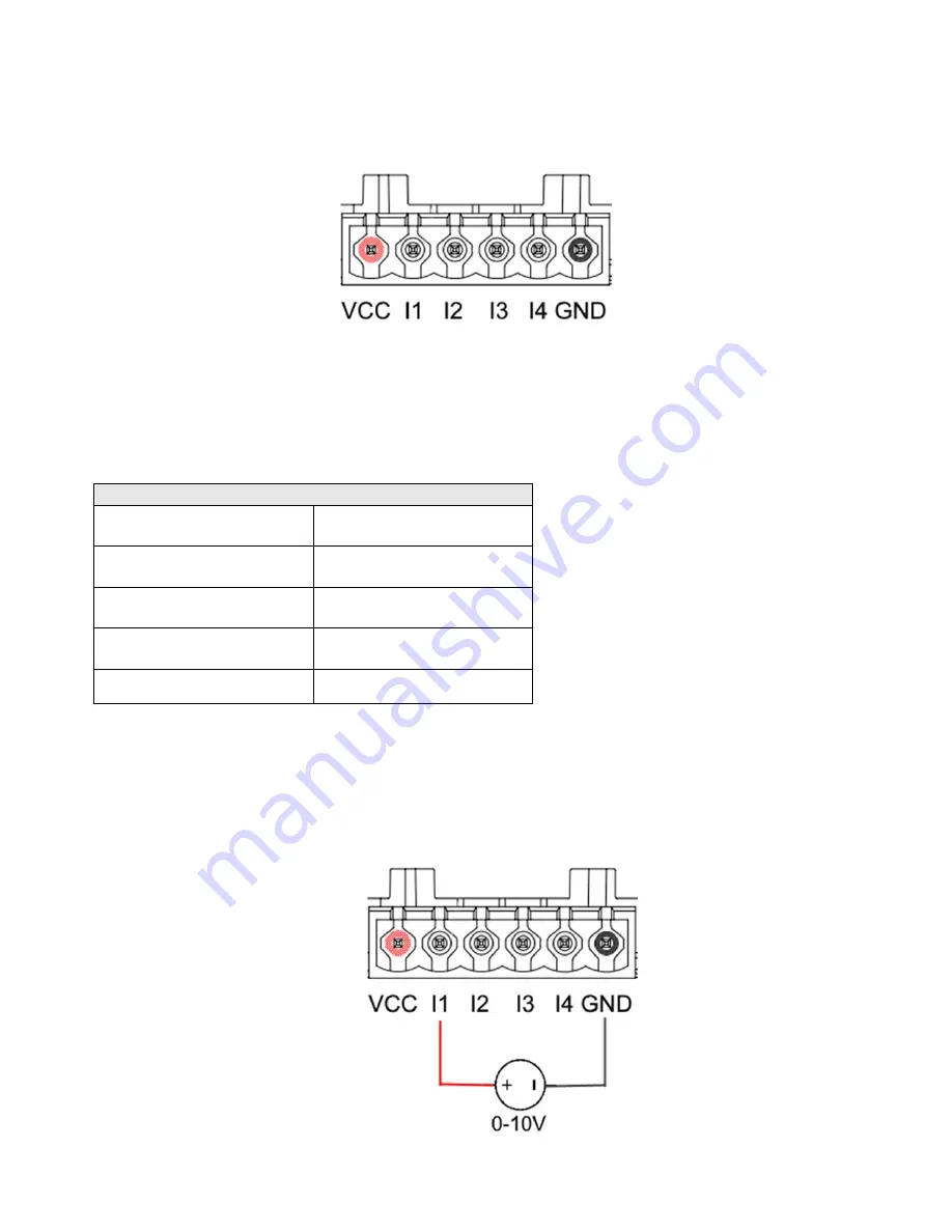
Inputs I/O: I1, I2, I3, I4
Figure 9E – DConnect BOX I/0 6-pole terminal board
The DConnect Box is equipped with 4
non-optoinsulated
voltage-controlled inputs.
They can be energised with positive DC voltages.
The Table describes the characteristics and the limits of the digital inputs:
Characteristics of the inputs (4 contacts)
Minimum switch-on
voltage [V]
2
Maximum switch-off
voltage [V]
0.5
Maximum admissible
voltage [V]
10
Current absorbed at 12V
[mA]
0.5
Accepted cable section
0.205-3.31 [mm²]
24-12 [AWG]
An example of connection of the input terminals is:
Applying a 0-10V voltage between input I1 and GND.
If the voltage is higher than 2V the input I1 will be active, if less than 0.5V it will be
deactivated.
Summary of Contents for DCONNECT BOX
Page 1: ...GUIDA DCONNECT BOX DCONNECT BOX GUIDE DCONNECT BOX DCONNECT BOX DCONNECT BOX...
Page 2: ...ITALIANO Pag 1 ENGLISH Pag 37 C 73 109...
Page 28: ...ITALIANO 26 Figura 9B Aggiornamento Active Driver Plus Sw 1 X...
Page 64: ...ENGLISH 62 Figure 9B Updating Active Driver Plus Sw 1 X...
Page 84: ...82 8 DAB 1 DAB 2...
Page 85: ...83 3 4 DAB...
Page 88: ...86 10 1 2 3 10 1 1 2...
Page 89: ...87 3 10 2 1 2 3 4...
Page 90: ...88...
Page 100: ...98 9 Active Driver Plus 1...
Page 109: ...107 14 11...
Page 120: ...118 8 DAB 1 DAB 2...
Page 121: ...119 3 4 DAB...
Page 124: ...122 10 1 2 3 10 1 1 2...
Page 125: ...123 3 10 2 1 2 3 4...
Page 126: ...124...
Page 136: ...134 9 B Active Driver Plus Sw 1 X...
Page 145: ...143 14 11...
Page 147: ......


