ENGLISH
74
3.2.2
Access by name via drop-down menus
The menus are selected via their specific name. The user accesses menu selection via the main menu, by
pressing or –.
The menu selection pages contains all the names of menus accessible, one of which is highlighted with a
bar (see Figure 10). The b and - can be used to move the highlighter bar to the menu required,
which is then entered by pressing SET.
Figure 10: Drop-down menu selection
The menus available are MAIN, USER, and MONITOR; after access to these, a fourth FULL MENU is
displayed, to enable full display of the menus selected. On selection of FULL MENU, a pop-up window is
displayed, requesting entry of a PASSWORD. The PASSWORD coincides with the combination of buttons
used for direct access, and enables the user to expand display of the menu from the password menu to all
those with lower priorities.
The menu order is: User, Monitor, Setpoint, Manual, Installer, Technical Assistance.
On selection of a password, the unlocked menus remain available for 15 minutes or until disabled manually
by means of the command “Hide advanced menus” displayed in the menu selection when a password is
entered.
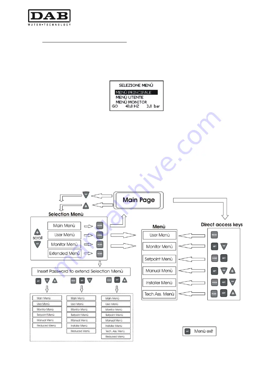
Figure 11 shows the functional scheme for menu selection.
The centre of the page shows the menus; the user can access these from the right using the button
combinations, or from the left by means of the drop-down menu selection system.
Figure 11: Optional menu access scheme
Summary of Contents for MCE-22/P
Page 278: ...274 1 276 2 279 3 280 4 282 5 283 6 4 20 284 7 285 8 286 9 287 10 290 11 290 12 292...
Page 279: ...275 IEC 60634...
Page 280: ...276 1 6 MCE 22 P MCE 15 P MCE 11 P 1 1 1...
Page 282: ...278 2 5 2 1 2 1 2 2 1 1 2 1 2 L L L 2 2 4 15...
Page 283: ...279 2 2 2 1 2 2 1 1 3 1 LN 2 2 3 1 3 4 4...
Page 284: ...280 A 3 3 2 2 1 2 4 3 1 UVW 2 2 4 3 50 60 200 1...
Page 286: ...282 4 2 2 3 Press e Flow 5 A B C D d1 d2...
Page 291: ...287 3 9 64 X 128 4 MODE SET 9 7 MODE 1 SET 8 3 EEprom SET 6 SET MODE...
Page 292: ...288 3 1 9 3 2 1 2 3 2 1 MODE SET MODE 8 2 2 5 5 5 2 2 9...
Page 294: ...290 3 2 2 10 SET 10 15 12 11...
Page 296: ...292 12 12 12 GO SB...
Page 297: ...293 4 4 1 Link 8 4 2 4 2 1 Link 2 Link 5...
Page 300: ...296 4 3 1 2 1 4 3 1 3 SET MODE LA RC FN MS FS FL AC AE O1 1 O2 2 4 4 ET 6 6 9 FL...
Page 326: ...322 BL 10 6 24 24 30 LP 180 200 HP OT TE 100 C 85 C OB BT 120 C 100 C OC 10 6 OF 10 6 30...
Page 327: ...323 8 8 1 PMW 4 2 8 2 8 3 8 3 SET EE EEprom FLASH...
Page 494: ...490 1 492 2 495 3 496 4 498 5 499 6 4 20 mA 500 7 501 8 502 9 503 10 506 11 506 12 508 13 523...
Page 495: ...491 IEC 364 inverter...
Page 496: ...492 1 Inverter inverter inverter 6 inverter MCE 22 P MCE 15 P MCE 11 P 1 1 1...
Page 499: ...495 2 2 2 1 inverter inverter 2 2 1 1 inverter 3 1 LN 2 inverter 2 PVC 3 inverter 1 3 inverter...
Page 502: ...498 4 2 2 3 Press Flow 5 A B C D d1 d2...
Page 507: ...503 3 9 oled 64 X 128 4 MODE SET 9 inverter 7 MODE 1 SET 8 3 EEprom SET 6 SET MODE...
Page 508: ...504 3 1 9 3 2 1 2 3 2 1 MODE SET Setpoint MODE 9 ONOMA TOY MENOY 2 Setpoint 2 5 5 5 2 2 9...
Page 512: ...508 12 12 12 GO SB FAULT...
Page 543: ...539 8 8 1 PMW 4 2 8 2 inverter 8 3 8 3 inverter SET EEPROM FLASH setpoint...
Page 599: ...595...


