ENGLISH
85
6. KEY TO INDIVIDUAL PARAMETERS
6.1 User
menu
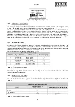
The USER MENU is accessed by pressing MODE (or via the selection menu by pr or - ). Within this
menu, again by pressing MODE, the following values are displayed consecutively.
6.1.1
FR: Display of rotation frequency
Current rotation frequency with electric pump is controlled, in [Hz].
6.1.2
VP: Display of pressure
System pressure measured in [bar] or [psi] depending on measurement system used.
6.1.3
C1: Display of phase current
Phase current of electric pump in [A]
A round flashing symbol may appear under the phase current C1symbol. This signals that the pre-alarm
threshold of maximum current allowed has been exceeded. If the symbol flashes at regular intervals it means
that the motor overcurrent protection is being activated and that it will probably be triggered. In this case it is
necessary to check the correct setting of the maximum current of the RC pump, see paragraph 6.5.1 and the
electric pump connections.
6.1.4
PO: Display of the power delivered
Power delivered to the electric pump in [kW].
A round flashing symbol may appear under the measured power PO symbol. This signals that the pre-alarm
threshold of maximum power allowed has been exceeded.
6.1.5 SM:
System
monitor
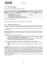
Displays the system status in the case of a multi-inverter installation. If there is no communication, an icon is
displayed, showing communication absent or interrupted. If there are several interconnected inverters, an
icon is shown for each. The icon bears the symbol of a pump with pump status indications below.
Depending on operating status, the item in Table 14 is displayed.
System display
Status
Icon
Status information below icon
Inverter in run
Symbol of pump running
Frequency implemented on 3 digits
Inverter in
standby
Symbol of static pump
SB
Inverter in fault
Symbol of static pump
F
Table 14: Display of SM system monitor
Summary of Contents for MCE-22/P
Page 278: ...274 1 276 2 279 3 280 4 282 5 283 6 4 20 284 7 285 8 286 9 287 10 290 11 290 12 292...
Page 279: ...275 IEC 60634...
Page 280: ...276 1 6 MCE 22 P MCE 15 P MCE 11 P 1 1 1...
Page 282: ...278 2 5 2 1 2 1 2 2 1 1 2 1 2 L L L 2 2 4 15...
Page 283: ...279 2 2 2 1 2 2 1 1 3 1 LN 2 2 3 1 3 4 4...
Page 284: ...280 A 3 3 2 2 1 2 4 3 1 UVW 2 2 4 3 50 60 200 1...
Page 286: ...282 4 2 2 3 Press e Flow 5 A B C D d1 d2...
Page 291: ...287 3 9 64 X 128 4 MODE SET 9 7 MODE 1 SET 8 3 EEprom SET 6 SET MODE...
Page 292: ...288 3 1 9 3 2 1 2 3 2 1 MODE SET MODE 8 2 2 5 5 5 2 2 9...
Page 294: ...290 3 2 2 10 SET 10 15 12 11...
Page 296: ...292 12 12 12 GO SB...
Page 297: ...293 4 4 1 Link 8 4 2 4 2 1 Link 2 Link 5...
Page 300: ...296 4 3 1 2 1 4 3 1 3 SET MODE LA RC FN MS FS FL AC AE O1 1 O2 2 4 4 ET 6 6 9 FL...
Page 326: ...322 BL 10 6 24 24 30 LP 180 200 HP OT TE 100 C 85 C OB BT 120 C 100 C OC 10 6 OF 10 6 30...
Page 327: ...323 8 8 1 PMW 4 2 8 2 8 3 8 3 SET EE EEprom FLASH...
Page 494: ...490 1 492 2 495 3 496 4 498 5 499 6 4 20 mA 500 7 501 8 502 9 503 10 506 11 506 12 508 13 523...
Page 495: ...491 IEC 364 inverter...
Page 496: ...492 1 Inverter inverter inverter 6 inverter MCE 22 P MCE 15 P MCE 11 P 1 1 1...
Page 499: ...495 2 2 2 1 inverter inverter 2 2 1 1 inverter 3 1 LN 2 inverter 2 PVC 3 inverter 1 3 inverter...
Page 502: ...498 4 2 2 3 Press Flow 5 A B C D d1 d2...
Page 507: ...503 3 9 oled 64 X 128 4 MODE SET 9 inverter 7 MODE 1 SET 8 3 EEprom SET 6 SET MODE...
Page 508: ...504 3 1 9 3 2 1 2 3 2 1 MODE SET Setpoint MODE 9 ONOMA TOY MENOY 2 Setpoint 2 5 5 5 2 2 9...
Page 512: ...508 12 12 12 GO SB FAULT...
Page 543: ...539 8 8 1 PMW 4 2 8 2 inverter 8 3 8 3 inverter SET EEPROM FLASH setpoint...
Page 599: ...595...


