ENGLISH
43
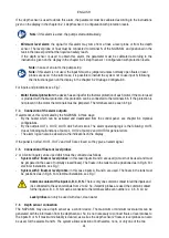
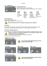
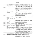
Note: the function with 3 floats is used in installations with deep narrow tanks that do not allow an
ample travel of the floats!
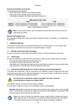
Operation with a depth sensor
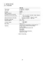
For configuration of filling with a depth sensor follow the instructions given on the display, in the chapter 8.2.1
8
CONTROL PANEL
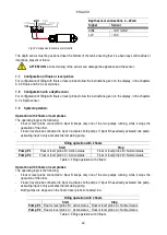
1 – Display
2 – Leds
System starting
System active
System in error
3 – Keys
Press to confirm and go to the next screen.
Press to access the selected menu page.
Press to cancel and return to the previous screen.
Press to leave the current menu page.
Press to browse the menu.
Press to increment the selected parameter.
Press and hold to increase the increment speed.
Press to browse the menu.
Press to decrement the selected parameter.
Press and hold to increase the decrement speed.
DISPLAY
1 – Header
Status: Describes the condition of the entire system (pumps
and panel).
Connectivity: Describes the connectivity status of the
system.
2 – Body
The central part of the display varies depending on the page
being viewed, and describes the necessary information.
3 – Footer
The lower part of the display contains the items “BACK” and
“CONFIRM”. In addition, further items will appear in relation
to the displayed menu page.
8.1
Initial configuration
The Initial Configuration procedure ends with the selection of the “Operating mode”, then
the installation continues with respectively chapters 8.2 Drainage Configuration or 8.3
Filling Configuration, depending on the operating mode selected.
When the panel is started for the first time, the initial configuration process is displayed on the screen.
Follow the on-screen instructions to complete the process.


