ITALIANO
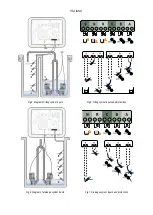
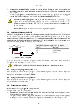
Fig.4: Diagram of filling system inputs
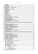
Fig.5: Filling system inputs and protections
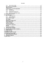
Fig.6: Diagram of drainage system inputs
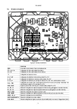
Fig.7: Drainage system inputs and protections
Page 1: ...MAINTENANCE FR INSTALLATIONS UND WARTUNGSANLEITUNGEN DE INSTRUCTIES VOOR INSTALLATIE EN ONDERHOUD NL INSTRUCCIONES DE INSTALACI N Y MANTENIMIENTO ES RU ASENNUS JA HUOLTO OHJEET FI INSTRUCTIUNI PENTRU...
Page 2: ...Pag 1 Pag 31 ITALIANO ENGLISH...
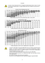
Page 3: ...ITALIANO Fig 1 Electrical connection of pumps and external capacitors Fig 2 Insertion of pump external capacitors Fig 3 Electrical connection to the supply line...
Page 4: ...ITALIANO Fig 4 Diagram of filling system inputs Fig 5 Filling system inputs and protections Fig 6 Diagram of drainage system inputs Fig 7 Drainage system inputs and protections...
Page 5: ...sonde di livello 9 6 8 Configurazione con Sensore di profondit 9 6 9 Funzionamento del sistema 9 7 FUNZIONE DRENAGGIO 10 7 1 Collegamenti elettrici pompa e alimentazione 10 7 2 Ingressi di controllo 1...
Page 6: ...a installazione 21 8 5 2 Struttura del menu 21 Storico Errori e Allarmi 22 Stato pompe 23 Modalit di scambio pompe 23 Stima portata acqua 23 Funzioni ausiliarie 24 Consumi e statistiche 24 Configurazi...
Page 7: ...E 2 3 Descrizione NGPANEL stato studiato e realizzato per il comando e la protezione dei gruppi di 1 o 2 pompe per drenaggio e riempimento 2 4 Riferimenti specifici di prodotto Per i dati tecnici si r...
Page 8: ...ti elettrici 5 1 Collegamento elettrico Attenzione osservare sempre le norme di sicurezza Nella rete di alimentazione deve essere previsto un dispositivo che assicuri la disconnessione completa nelle...
Page 9: ...ensatore esterno di avvio per pompe monofase con condensatore esterno Per pompe P1 e P2 KK1 KK2 Ingresso protezione termica per il motore delle pompe P1 e P2 A B C Morsetti collegamento ingressi digit...
Page 10: ...m 70 m 80 m 90 m 100 m 120 m 140 m 160 m 180 m 200 m 4 A 1 5 1 5 1 5 1 5 1 5 1 5 1 5 1 5 2 5 2 5 2 5 2 5 4 4 4 8 A 1 5 1 5 1 5 1 5 2 5 2 5 2 5 4 4 4 6 6 6 10 10 12 A 1 5 1 5 2 5 2 5 4 4 4 6 6 6 10 10...
Page 11: ...l quadro NGPANEL pu essere utilizzato per la realizzazione di impianti di riempimento Come ingressi di controllo possono essere usati indifferentemente galleggianti sonde di livello o un sensore di pr...
Page 12: ...ndicate a display nel capitolo 8 3 Configurazione Riempimento Per ingressi e protezioni vedi Fig 5 Protezione contro la marcia a secco il quadro possiede un ingresso per la protezione contro la marcia...
Page 13: ...dit anche 2 galleggianti o sonde di livello per gli allarmi R N Il sistema permette di selezionare entrambi gli allarmi nessuno o solo uno dei due Fig 9 Collegamento sensore di profondit Collegamenti...
Page 14: ...ione riempimento con sensore di profondit seguire le istruzioni indicate a display nel capitolo 8 3 1 Sensore di profondit 7 FUNZIONE DRENAGGIO Il quadro NGPANEL pu essere utilizzato come quadro di co...
Page 15: ...iungere in sicurezza Se si utilizza il sensore di profondit per ottenere questo allarme va tarato il parametro verso le istruzioni indicate a display nel capitolo 8 2 1 Sensore di profondit Configuraz...
Page 16: ...sensore di profondit anche 2 galleggianti o sonde di livello per gli allarmi R N Il sistema permette di selezionare entrambi gli allarmi nessuno o solo uno dei due Fig 10 Collegamento sensore di profo...
Page 17: ...pompe Qualora l ingresso B abbia gi azionato una pompa l attivazione dell ingresso C mette in funzione solo la pompa restante Entrambe le pompe si spengono sul galleggiante o sonda di livello collegat...
Page 18: ...sistema pompe e quadro Connectivity Descrive lo stato della connettivit del sistema Solo se prevista dal prodotto 2 Body La parte centrale del display varia a seconda della pagina visualizzata e ne d...
Page 19: ...sce ritentare con il tasto Seguire le istruzioni indicate su smartphone Una volta avvenuta la connessione tra il quadro e lo smartphone sul display appare un popup di conferma Per annullare la procedu...
Page 20: ...o Altezza serbatoio Impostare l altezza del serbatoio di cui si dispone che non pu essere superiore al fondo scala del sensore La scelta dei valori parte da un minimo di 0 5 m 1 6 ft ad un massimo di...
Page 21: ...enti intervalli Alla ripartenza Ogni 2 ore Ogni 4 ore Ogni 8 ore Ogni 12 ore Ogni 16 ore Ogni 20 ore Ogni 24 ore Mai La scelta della modalit di scambio necessaria per impedire l usura di una sola pomp...
Page 22: ...ro scelto ed alla tensione di alimentazione Alla prima istallazione il tasto inibito in quanto l inserimento di un valore obbligatorio Tipo di controllo usato I controlli disponibili sono i seguenti S...
Page 23: ...l troppo pieno e per emergenza serbatoio vuoto questi inibiscono gli allarmi impostati con il sensore di profondit La scelta di predisporre entrambe le protezioni per una maggiore sicurezza dell impia...
Page 24: ...lit non viene abilitata durante la Configurazione Riempimento o Drenaggio non pi possibile attivarla Tale operazione sar possibile solo tramite il ripristino dei dati di fabbrica Il sistema pronto Tut...
Page 25: ...ve una effettiva condizione del sistema 8 5 1 Prima installazione Solo alla prima installazione appare il pop up Funzionamento del sistema di pompaggio L attivazione del sistema concessa tramite Contr...
Page 26: ...Il sistema fornisce complessivamente tre tipologie di segnalazioni in ordine di gravit Avviso Errore Pericolo Rileva un malfunzionamento al sistema o alle pompe ma questo non ne impedisce il funzionam...
Page 27: ...aria per impedire l usura di una sola pompa Stima portata acqua Questa funzionalit non visibile a meno che non sia stata attivata in fase di Configurazione Drenaggio o Configurazione Riempimento Tale...
Page 28: ...possibile proseguire con l azzeramento delle ore lavorate e dei riavvii esclusivamente per i conteggi parziali Tale operazione eseguibile sia sulla Pompa 1 sia sulla Pompa 2 che su entrambe le pompe...
Page 29: ...far fermare il motore e non potr essere in alcun modo annullata Sistema La schermata mostra sulla destra i parametri che identificano il quadro e le sue versioni firmware mentre sulla sinistra un codi...
Page 30: ...ima di iniziare un qualsiasi intervento sul sistema disconnettere l alimentazione elettrica Il sistema esente da operazioni di manutenzione ordinaria Si raccomanda di non forzare sui vari particolari...
Page 31: ...ppo alta Verificare le condizioni della linea di alimentazione del quadro F0 010 F0 024 EEPROM non letta scritta correttamente 1 Guasto scheda Contattare il Servizio Clienti 2 Problema firmware Contat...
Page 32: ...e la tensione d ingresso coincida con quella indicata sulla targhetta dati delle pompe in uso W0 001 Pompa ferma per un tempo superiore a quello di intervento della protezione anti lock 1 Attendere ch...
Page 33: ...controllo o tramite modalit manuale richiede pi di 8 avvii al minuto per una delle due pompe 1 In caso di controllo tramite galleggianti o sonde di livello usare il galleggiante di arresto delle pompe...
Page 34: ...potenza nominale pompe 5 5 kW 1 5 kW a 3 560 600 3 380 440 3 280 V a 1 110 127 1 220 230 V Temperatura ambiente 10 40 C Temperatura di stoccaggio 25 C 55 C Umidita relativa dell aria 50 90 a 40 C a 2...
Page 35: ...Connection of floats or level probes 38 6 7 Depth sensor connection 39 6 8 Configuration of floats or level probes 39 6 9 Configuration with a depth sensor 39 6 10System operation 39 7 DRAINAGE FUNCTI...
Page 36: ...rst installation 50 8 5 2 Menu structure 50 Error and Alarm Log 51 Pump status 51 Pump exchange mode 52 Water flow rate estimation 52 Auxiliary functions 52 Consumption and statistics 52 Device config...
Page 37: ...ONTROL DEVICE 2 3 Description NGPANEL has been designed and manufactured for the control and protection of sets of 1 or 2 pumps for draining and filling 2 4 Specific product references For technical d...
Page 38: ...tion Attention always respect the safety regulations In the power mains there must be a device that ensures complete disconnection in overvoltage category III conditions Make sure that the mains volta...
Page 39: ...trical connection for external starting capacitor for single phase pumps with external capacitor For pumps P1 and P2 KK1 KK2 Thermal protection input for the motor of pumps P1 and P2 A B C Terminals c...
Page 40: ...0 m 30 m 40 m 50 m 60 m 70 m 80 m 90 m 100 m 120 m 140 m 160 m 180 m 200 m 4 A 1 5 1 5 1 5 1 5 1 5 1 5 1 5 1 5 2 5 2 5 2 5 2 5 4 4 4 8 A 1 5 1 5 1 5 1 5 2 5 2 5 2 5 4 4 4 6 6 6 10 10 12 A 1 5 1 5 2 5...
Page 41: ...supply use terminals L1 and N In the case of three phase power supply use terminals L1 L2 N See Fig 3 6 FILLING FUNCTION The NGPANEL can be used for making filling systems As control inputs floats le...
Page 42: ...operation signalled by a float immersed in the tank of the pumps controlled by the panel The device must be connected to the S contact of the NGPANEL and positioned in the tank at a level that ensure...
Page 43: ...the tank ensuring that it is above any solid residue or impurities present or future ATTENTION incorrect wiring of the sensor can damage the appliance and the sensor 6 8 Configuration of floats or lev...
Page 44: ...ust be taken Floats and level probes cannot be used at the same time Level probes can only be used with clear clean water If the depth sensor is being used the maximum level and minimum level alarms c...
Page 45: ...ated and deactivated from the control panel see chapter 8 4 Optional configurations By the outputs OUT1 OUT2 OUT3 which short circuit The alarm operating logic is the following OUT1 closes following m...
Page 46: ...s the operation of the other Float or level probe connected to input C activates both pumps If input B has already activated one pump activating input C only activates the remaining pump Filling opera...
Page 47: ...selected parameter Press and hold to increase the decrement speed DISPLAY 1 Header Status Describes the condition of the entire system pumps and panel Connectivity Describes the connectivity status o...
Page 48: ...e connection fails try again with the key Follow the instructions on your smartphone Once the connection between the panel and the smartphone has been made a confirmation pop up appears on the display...
Page 49: ...be higher than the full scale value of the sensor The choice of values ranges from a minimum of 0 5 m 1 6 ft to a maximum of 30 m 98 4 ft Configuration with protection levels With the depth sensor it...
Page 50: ...ry 12 hours Every 16 hours Every 20 hours Every 24 hours Never The choice of exchange mode is necessary to prevent wear of a single pump Enable water flow rate estimation function To enable this funct...
Page 51: ...m of 0 5 A default value to a maximum of 12 0 A 20 0 A or 29 0 A depending on the selected panel and on the supply voltage When first installed the key is inhibited as entering a value is mandatory Ty...
Page 52: ...rflow and empty tank emergency have already been provided these inhibit the alarms set with the depth sensor The decision to provide both protections is for greater system safety Then proceed to set t...
Page 53: ...his function is not enabled during the Filling or Draining Configuration it can no longer be activated This will only be possible by resetting to the factory data The system is ready All the parameter...
Page 54: ...It does not describe an actual condition of the system 8 5 1 First installation The Pumping System Operation pop up appears only on first installation Activation of the system is allowed via Manual Co...
Page 55: ...but this does not prevent operation E g Overflow It detects a malfunction that prevents the system or pumps from operating normally E g Overcurrent It detects a critical issue in the system or pumps...
Page 56: ...ent Confirm twice to delete Water flow rate estimation selecting this option allows the Water flow rate estimation menu to be masked from the main menu screens If this function is not enabled during D...
Page 57: ...guration with DConnect App ATTENTION Make sure the system is secured before proceeding The configuration requires double confirmation to continue This is because the action will cause the motor to sto...
Page 58: ...RAL SYSTEM RESET To reset the NGPANEL hold down the 4 keys on the panel simultaneously for at least 1 sec This operation does not delete the settings saved by the user 9 1 Restoring the factory settin...
Page 59: ...tion by one of the two pumps although it has not been started 1 Switch off the panel and check whether the left hand contactor is stuck in the closed position If it is replace it with one of the same...
Page 60: ...Depth sensor error 1 Check that the sensor is connected to input AIN1 2 Check that the sensor is not damaged and that the connection cable to the panel is intact F1 012 The panel tried to start one o...
Page 61: ...of the flood sensor connected to AIN2 Check that the sensors are intact 2 Fault on the board Contact Customer Service W0 008 No input voltage Switch the panel back on to restore normal operation W0 00...
Page 62: ...mum rated power of the pumps 5 5 kW 1 5 kW at 3 560 600 3 380 440 3 280 V at 1 110 127 1 220 230 V Environment temperature 10 40 C Storage temperature 25 C 55 C Air relative humidity 50 90 at 40 C at...
Page 63: ...2 Groot Bijgaarden Belgium 1702 Groot Bijgaarden Belgium info belgium dwtgroup com info belgium dwtgroup com Tel 32 2 4668353 Tel 32 2 4668353 DAB PUMPS IBERICA S L DAB PUMPS IBERICA S L Calle Verano...