background image


25 

10. OPTION 

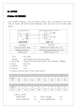
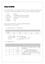
#Option-02 (RS232C)   

 
  Since RS232C Interface is very sensitive of electric noise. So please do the wiring 

from AC Power and electric wires separately. Also you must use the shield calbe 
always.   


Indicator 

Host PC 

TX(Transmission Data) 

RXD(Receive Datea), No.2 Pin 

RX(Receive Datea) 

TXD(Transmission Data), No.3 Pin 

GN(Ground) 

GND(Ground), 5 Pin 


1.


TYPE   

: EIA-232C 

Method  

: Half-duplex, asynchronous method.   

2.


Baud-rate 

: Select one of 2400, 4800, 9600, 19200, 38400, 57600bps   

3.


Parity   

: No Parity 

4.


Data bit  

: 8 bit 

5.


Stop bit  

: 1bit 

6.


Stream mode (Ex. Data +1234.5 transmission ) 


1B

CODE  BYTE1  BYTE2  BYTE3  BYTE4  BYTE5  BYTE6  BYTE7  BYTE8 

2B

ASCII 

HEX 

53H 

54H 

2CH 

4EH 

54H 

2CH 

2BH 

30H 


CODE  BYTE9  BYTE10  BYTE11  BYTE12  BYTE13  BYTE14  BYTE15  BYTE16 

ASCII 

CR 

LF 

3B

HEX 

31H 

32H 

33H 

34H 

2EH 

35H 

0DH 

0AH 


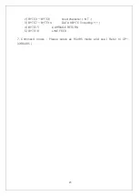
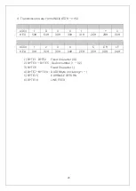
1) BYTE1, BYTE2   

. DATA Stable 


: S T        . DATA Unstable 


: U S   

    . DATA OVERFLOW   

: O L        . DATA UNDERFLOW 

: U L   

Summary of Contents for DN-70

Page 1: ...MODEL DN 70 DIGITAL INDICATOR USER MANUAL DACELL CO LTD Address 37 9 Cheoksan 5gili Nami Myeon Seowon gu Cheongju city Chung buk TEL 82 43 260 2242 FAX 82 43 260 2245 http www dacell com E Mail info d...

Page 2: ...Panel 6 6 Wiring Diagram 8 7 Components Function 9 7 1 How to use Hold mode 9 7 2 How to use comparison output function 10 8 Setting mode 12 8 1 Types of Setting mode Set up 12 8 2 Function mode Func...

Page 3: ...ration systems are adopted Calibration by actual load standard weight and calibration by rated output of sensor mV V 1 2 Hold Peak Hold You can choose peak hold and sample hold as per your need 1 3 Co...

Page 4: ...is less dust and Keep it out of direct air including salt and ion Do not use when there is inflammable gas or heavy machinery and smog Ground earth terminal Make wire separately from power system wiri...

Page 5: ...o 0 5 V Span 50ppm Front Panel Measured value display 7 segment Status display Red LED 5pcs Key Switch 4pcs Comparison output Upper limit HI Lower limit LO Normal OK Output Contact Capacity AC 250V 3A...

Page 6: ...l be 0V 4mA as well SET UP Mode Once this is pressed on the Function Set up Mode you will return to the measuring mode Measuring Mode Once this Key is pressed the lower limit setting value will be dis...

Page 7: ...be brazing or used with 1 terminal 24V DC24V Main Power EXC Sensor Supply Voltage Connection Terminal EXC Sensor Supply Voltage Connection Terminal SIG Sensor Ouput Signal Connection Terminal SIG Sen...

Page 8: ...to the impulse voltage or surge If possible please keep it as an independent ground This must be used in the area with heavy noise If the ground is made with other device it will be affected by noise...

Page 9: ...8 6 Wiring Diagram Wiring Diagram Example External Input PLC Connection...

Page 10: ...among the measured values Peak hold mode It is to hold and display the maximum value of direction Absolute peak hold mode It is to hold and display the maximum value of the absolute value 2 Sample ho...

Page 11: ...wer limit setup value Measured value Upper limit setup value RY3 ON OK 2 High limit mode Measured Value RY1 setup value RY1 ON Measured Value RY2 setup value RY2 ON Measured Value RY3 setup value RY3...

Page 12: ...11...

Page 13: ...de Digital calibration mode Actual load calibration mode Function mode Acess to each function setup mode Please refer 8 2 function mode Digital calibration mode It is to calibrate into the sensor s ou...

Page 14: ...13 8 2 Function mode 1 How to set function Measuring mode While key is being Press press key...

Page 15: ...14 2 How to set RELAY data Decision mode Decision mode mode 0 Limit mode Low High limit mode mode 1 2 Measuring mode Press key Input value...

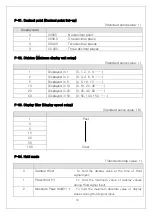
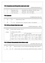
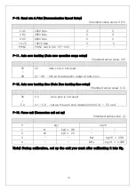
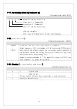
Page 16: ...acity 19999 99999 10000 F 09 ID Number 0 32 0 F 10 Baud rate 2400 4800 9600 19200 38400 57600 9600 F 11 Auto zero tracking 0 99 0 F 12 Auto zero tracking time 0 0 5 0 sec 0 0 F 13 Force unit Kg kg N b...

Page 17: ...splayed in 5 0 5 10 15 10 Displayed in 10 0 10 20 30 20 Displayed in 20 0 20 40 60 50 Displayed in 50 0 50 100 150 F 03 Display filter Display speed setup Standard setup value 16 Display data Setting...

Page 18: ...lied F 08 DAC zero Analog Outupt value setup Standard setup value 10000 Display data Setting 19999 Analog output capacity set up If Setting value 10000 Display data F 07 setting data V_05V V_10V V_02A...

Page 19: ...y data Setting 00 00 Auto zero is not used 99 01 99 Set up the operation range of auto zero F 12 Auto zero tracking time Auto Zero tracking time setup Standard setup value 0 0 Display data Setting 00...

Page 20: ...alue is registered When Base value 10 00 the display is 10 00 if you press ZERO button When setting the reference value the comparison output operation is not based on whether the existing display dat...

Page 21: ...calibration for easier calibration Measuring Mode While key is being pressed press key Displays Function Mode Displays Sensor Output Calibration State Displays Rated Output value Input State Displays...

Page 22: ...of the sensor can be increased In the actual load calibration mode calibration is possible at the forward output of the sensor and calibration is not possible at the reverse output of the sensor Measu...

Page 23: ...RESTORE Restore the current set up state Measuring mode While key is being pressed Press key After 1 sec for display Display Please select YES or NO by using key YES SAVE DATA NO Do not save DATA 1 DA...

Page 24: ...ck At the first stage please start while the power is OFF Related Function when Lock is set Function related to calibration Power is OFF While key is being pressed please turn the power ON Please keep...

Page 25: ...oes up at a regular ratio or zero returns are not made Loadcell faulty Check load cell s insulation resistance Loadcell connection is insufficient Check the wiring between load cell and the main devic...

Page 26: ...d 5 Pin 1 TYPE EIA 232C Method Half duplex asynchronous method 2 Baud rate Select one of 2400 4800 9600 19200 38400 57600bps 3 Parity No Parity 4 Data bit 8 bit 5 Stop bit 1bit 6 Stream mode Ex Data 1...

Page 27: ...26 2 BYTE3 BYTE6 fixed character N T 3 BYTE7 BYTE14 DATA 8 BYTE including 4 BYTE15 CARRIAGE RETURN 5 BYTE16 LINE FEED 7 Command mode Please setup as RS485 mode and use Refer to OP 03 RS485...

Page 28: ...bit 1bit Please set up the device No referring to INDICATOR Manual Can setup from 1 to 32 channel 7 Command Form PC INDICATOR 4BCODE BYTE1 BYTE2 BYTE3 BYTE4 BYTE5 5BASCII I D 0 1 P HEX 49H 44H 30H 31H...

Page 29: ...H 54H 30H 30H 31H 2CH 2BH 30H CODE BYTE9 BYTE10 BYTE11 BYTE12 BYTE13 BYTE14 BYTE15 BYTE16 ASCII 1 2 3 4 5 CR LF 7BHEX 31H 32H 33H 34H 2EH 35H 0DH 0AH 1 BYTE1 BYTE2 Fixed Charactor ID 2 BYTE3 BYTE5 Dev...

Reviews: