background image

DACELL CO., LTD 

http://www.dacell.com


TEL:+82-43-2602242, FAX : +82-43-2602245 


11


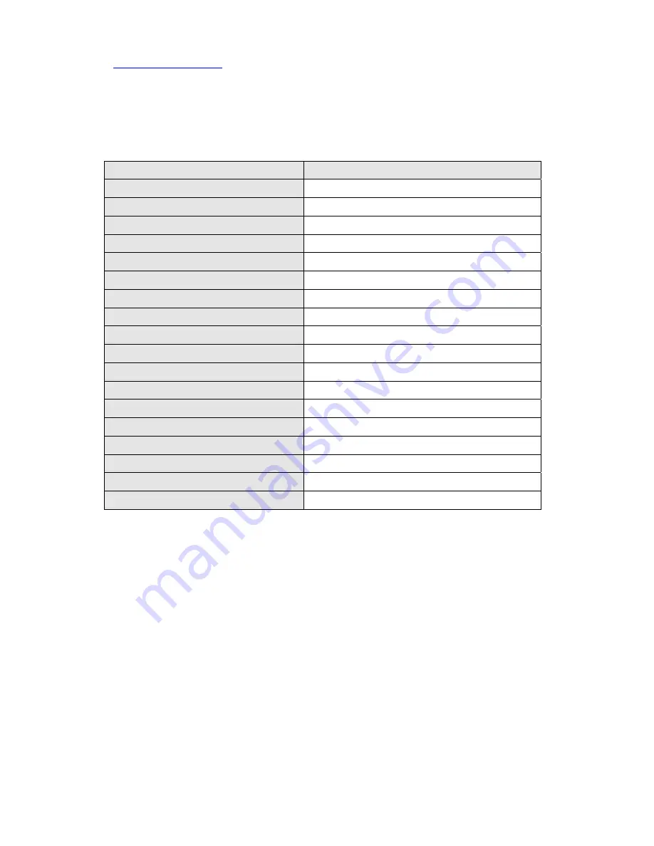
8. TECHNICAL DATA


item


data


allowed time temperature 

40 

 80


operating temperature 

    0  

 50  


power of sensor 

5Vdc or 10Vdc 

input signal type 

   1 

 3mV/V 

max. load current 

10Vdc/60

, 5Vdc/120


frequency response 

Max 5


analog output 

0

10V,0

20

,1

5V, 4

20


relay output 

220V/5A (a,b contact) 

relay response 

Max 66

/sec 

nonlinear characteristics 

±

0.02

/F.S 

temperature coefficient 

±

0.02

F.S/


display size 

14

×8


sampling time 

15 times/sec, 30 times/sec 

filter frequency 

1

, 10

, 100

, 4


short protection circuit 

protection circuit (insert) 

max. display range 

-19999 

 19999 

size 

w 96

×h 48

×d 126


power 

110Vac, 220Vac (50

60


9. Unit Label change


      * Unit label is optional.   
      * In the case of exchanging label, refer to as follows   
        1, Separate P.C.B from the case.   
        2, Remove Conventional unit label and then adhere new   label.   


3, Put together indicator in reverse process.   


Summary of Contents for SM110

Page 1: ...LTD http www dacell com TEL 82 43 2602242 FAX 82 43 2602245 1 DIGITAL INDICATOR SM110 150 INSTRUCTION MANUAL DACELL CO LTD TEL 82 43 260 2242 FAX 82 43 260 2242 WEBSITE http www dacell com EMAIL info...

Page 2: ...ricity DACELL is not liability for mistake to use that change a property voluntarily change design adjustment voluntarily user carelessness cause defect 1 Installation 1 Product Spec Spec 96 48 3 78 1...

Page 3: ...on mode 3 ANALOG OUTPUT 4 GND 5 Analog output is as following voltage or current DIP switch 5 on voltage output DIP switch 5 off current output ON Voltage Output 0 5V 1 5V 0 10V 2 10V OFF Current Outp...

Page 4: ...ed on only one in accordance with kind of sensor Under 0 700mV V or over 3 500mV V are option SOFTWARE setting In cal mode input as follows according to sensor output 5 RELAY OUTPUT A NO and B NC cont...

Page 5: ...Display operation mode of high relay HI setting Confirm and adjust high data operation Display operation mode of low relay LO setting Confirm and adjust low data FS setting Confirm and adjust full sca...

Page 6: ...2 3 4 5 6 7 8 9 0 Input 8 Input data After setting up must press key therefore become input Auto zero 9 Sensor No load state 0V 4 10 Display 0 4 PROTECTION mode Use this mode for protection and secur...

Page 7: ...AUTO CALIBRATION mode Convenience to use when do not know calibration data of sensor or displayed the measurement value differently 1 Adjust zero point of indicator 2 Apply known load to sensor Large...

Page 8: ...calibration Check function Relay output analog output reset hold peak Press key data protection mode 5 HARDWARE 1 Selection of AC input power 1 Separate P C B from case 2 The following label is exist...

Page 9: ...calibration execution 1 mV V range 0 700 1 249 mV V 1 5 mV V range 1 250 1 749 mV V 2 mV V range 1 750 2 499 mV V 3 mV V range 2 500 3 500 mV V 2 Adjustment of display time and measurement data unit 1...

Page 10: ...y x 1 x x display to signal and display indicate opposite ex 20mA display 760 0 x x 0 x standard type Display 0 trace minute signal to 0 Tracking mode of zero point x x 1 x Display 0 display minute si...

Page 11: ...ct relay response Max 66 sec nonlinear characteristics 0 02 F S temperature coefficient 0 02 F S display size 14 8 sampling time 15 times sec 30 times sec filter frequency 1 10 100 4 short protection...

Page 12: ...rt of sensor in output line Check DIP switch about sensor output Check sensor wiring Display change Exchange of sensor input line data setting error Check sensor connection refer to 6 3 Not able to se...

Reviews: