background image

Verifying the Package Contents ...................................8

Installing the Cooktop ...................................................8

Connecting the Gas Line..............................................8

Assembling the Burners ...............................................9

Verifying the Correct Setup ........................................10

Installation Checklist ...................................................11

Replacement Parts List................................................... 12

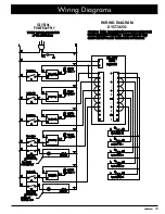
Wiring Diagrams .............................................................. 14

Table of Contents

Before You Begin...

Important Safety Instructions ......................................1

Important Information About Safety Instructions ..........1

General Safety Precautions .........................................2

Electrical Requirements ...............................................3

Gas Supply Requirements ...........................................3

Installation Specifications ............................................4

Product Dimensions .....................................................4

Cabinet and Countertop Layout ...................................6

All specifications are subject to change without notice. Dacor


assumes no liability for changes to specifications.

Important

Installer:

 In the interest of safety and to minimize problems, read this 

Installation Instruction

 manual completely and   


       carefully before you begin the installation process. 


• Leave this 

Installation Instructions

 with the consumer.


• Write the 

Product Data Label 

information inside the 

Use and Care 

manual for the consumer’s future reference.

Consumer:

 Keep these 

Installation Instructions

 for future reference and for the local electrical inspector’s use.


   Note:

 Dacor


®

 is not responsible for service required to correct a faulty installation.

© 2015 Dacor, all rights reserved.

If You Need Help...

If you have questions or problems with installation, contact 

your Dacor dealer or the Dacor Customer Service Team. For 

repairs to Dacor appliances under warranty call the Dacor 

Distinctive Service line. Whenever you call, have the model 

and serial number of the appliance ready. The model and 

serial number are printed on the product data label. 

Dacor Customer Service

Phone:  (800) 793-0093 ex. 2813 (U.S.A. and Canada) 

Monday — Friday 6:00 

a

.

m

.

 to 5:00 

p

.

m

.

 Pacific Time

Website: www.dacor.com

Dacor Distinctive Service (repairs under warranty only)

Phone:  (800) 793-0093, ex. 2822 (U.S.A. and Canada) 

Monday — Friday 6:00 

a

.

m

.

 to 5:00 

p

.

m

.

 Pacific Time

Customer Service Information
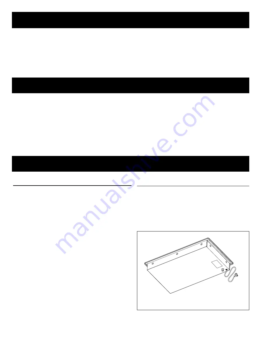
Product Data Label

The product data label is attached to the chassis, under-

neath the unit.
The label contains:
 

• the model number and serial number


• the electrical requirement and gas supply    


  requirements

Model Shown:

DYCT365G

Product data 

label

Product Data Label Location

Summary of Contents for Discovery DYCT304GWNG

Page 1: ...Installation Instructions Discovery Gas Cooktop Models DYCT304G DYCT365G Part No 108861 Rev A...

Page 2: ...r Keep these Installation Instructions for future reference and for the local electrical inspector s use Note Dacor is not responsible for service required to correct a faulty installation 2015 Dacor...

Page 3: ...ppliance Do not touch any electrical switch or use any electri cal devices including the telephone in your building From a neighbor s phone immediately call the gas supplier Follow the gas supplier s...

Page 4: ...of the appliance WARNING General Safety Precautions To reduce the risk of fire electric shock or serious injury or death when using your appliance follow basic safety precautions including the followi...

Page 5: ...for high altitude operation have an H at the end of the model number listed on the product data label Units equipped for LP operation have LP in the model number listed on the product data label See t...

Page 6: ...DYCT304G All tolerances 1 16 1 6 mm unless otherwise noted 13 16 2 1 cm 3 3 4 9 5 cm Gas inlet Power cord Chassis Front of cooktop Top panel overhang 2 1 8 5 4 cm 5 8 1 6 cm 30 76 2 cm 21 53 3 cm 27...

Page 7: ...cord in Chassis Front of cooktop Top panel overhang 2 1 4 5 7 cm 36 76 2 cm 21 53 3 cm 4 10 2 cm Chassis height 19 1 2 49 5 cm 33 5 8 85 4 cm Including raised embosses on sides of chassis DYCT365G Po...

Page 8: ...stalled The 40 inch 101 6 cm power cord must be able to reach an electrical outlet and that electrical outlet must be easily accessible after the cooktop is installed Access to the underside of the co...

Page 9: ...Series Countertop Cutout Dimensions All tolerances 1 16 0 1 6 mm unless otherwise noted Installation Type C Minimum D E F DYCT304G with no downdraft 2 7 8 7 3 cm 19 3 4 50 2 cm 27 5 8 70 1 cm 7 1 2 1...

Page 10: ...apply excessive pressure when tightening gas connections and fittings Do not use Teflon tape or plumber s putty on flexible gas line connections Before use test the gas lines for leaks as instructed...

Page 11: ...until it drops completely into place The burners will not function properly unless all of the burner pieces are correctly seated 3 Gently set the grates on top of the spill tray Make sure that the rub...

Page 12: ...e flame height SimmerSear burners turn the control knob to the simmer setting and make sure the low level flame can be adjusted When the unit is installed correctly the flame will burn steadily It wil...

Page 13: ...ce for the cooktop located and installed according to these instructions and in accordance with all applicable codes See page 3 Has the gas supply inlet pressure been measured to ensure that it does n...

Page 14: ...PN 108900 PN 108900 Grate small PN 108901 Grate support feet 4 PN 103712 PN 103712 Stainless steel cleaner PN A302 PN A302 Model DYCT365G See the Burner Parts and Cooktop Layout on right Burner Part D...

Page 15: ...r Location LR RR CR LF RF CF DYCT365G Trim ring Spill tray Grate SimmerSear control knobs LR CR RR LF CF Burner control knob Trim ring Grate Spill tray LR RR LF RF Trim ring SimmerSear control knob Bu...

Page 16: ...s AFTER SERVICING VERIFY PROPER OPERATION 120V 60Hz POWER SUPPLY CAUSE IMPROPER AND DANGEROUS OPERATION WHEN SERVICING CONTROLS WIRING ERRORS CAN CAUTION LABEL ALL WIRES PRIOR TO DISCONNECTION WIRING...

Page 17: ...K INDICATOR LED RR BK INDICATOR LED CR BK INDICATOR LED LR ISOLATOR BOARD P N 106104 L1 IGNITOR LR BURNER W N RE IGNITOR RED NO SWITCH S1 BK BK BK W RE IGNITOR IGNITOR CR BURNER N S2 BK NO SWITCH L1 R...

Page 18: ...Dacor 14425 Clark Avenue City of Industry CA 91745 Phone 800 793 0093 Fax 626 403 3130 www dacor com...

Reviews: