background image

6

Cabinet and Countertop Layout

 WARNING

•  To reduce the risk of personal injury caused by 

reaching over a hot appliance, avoid locating cabinet 

storage space directly above the cooktop.

•  Failure to meet or exceed the maximum and mini-

mum dimensions/clearances stated in these instruc-

tions may result in a fire hazard.

•  Follow the countertop manufacturer’s instructions 

regarding the minimum corner radius, use of heat 

reflective tape, reinforcement of corners, etc.

•  Carefully check the location where the cooktop will be 

installed. For best performance, the cooktop should be 

placed away from drafts that may be caused by doors, 

windows, and heating and air conditioning vents. 

•  This appliance is to be used in conjunction with a suit-

able vent hood or approved Dacor downdraft vent.

Refer to the following illustrations and notes for clearance 

allowances.

Model

(A) Minimum

(A) Recommended

DYCT304G

30” (76.2 cm)

36” (91.4 cm)

DYCT365G

36” (91.4 cm)

42” (106.7 cm)

Installation Specifications

Model

(B) Minimum to allow for clearance of 

hold-down brackets

DYCT304G

29 in (73.7 cm)

DYCT365G

35 1/4 in (89.5 cm)

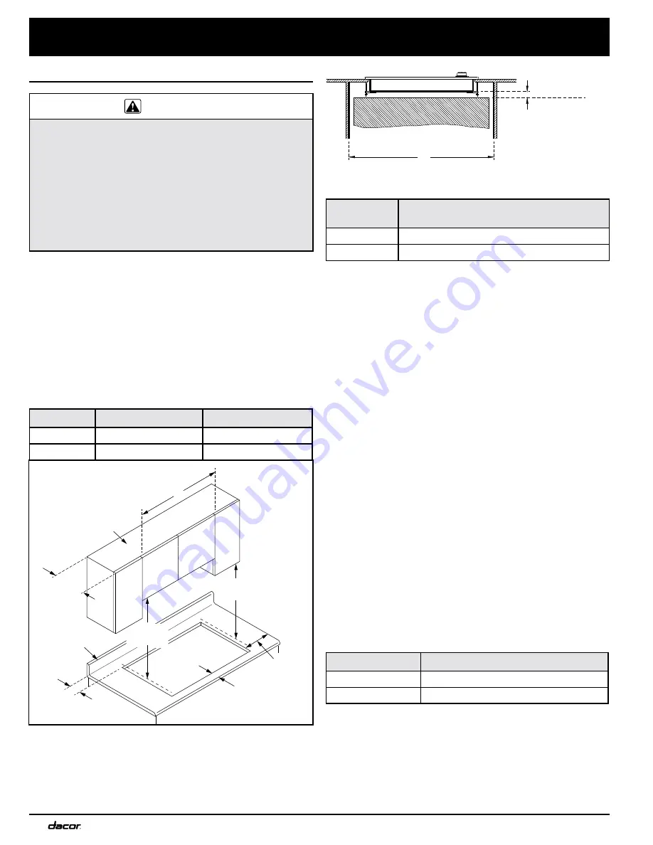
•  Allow a minimum 1/4” (6 mm) clearance between the 

bottom of the cooktop chassis and all combustible sur-

faces, including the upper edge of a drawer inside the 

countertop cabinet below the cooktop.

•  The gas supply piping, gas shut-off valve, and the elec-

trical outlet must be located so they do not interfere 

with the cooktop after it is installed. If installing another 

appliance in the cabinet below, allow for the routing of 

gas and electrical service behind it.

The installation must allow for the following:

•  Access to the gas shut-off valve and regulator when 

the unit is installed. 

•  The 40-inch (101.6 cm) power cord must be able to 

reach an electrical outlet, and that electrical outlet must 

be easily accessible after the cooktop is installed. 

•  Access to the underside of the cooktop for service and 

inspection purposes.

•  Clearance inside the counter to allow for correct instal-

lation of the hold-down brackets.

To allow underneath access to the utilities and cooktop 

bottom, a fixed shelf should 

not

 be installed below the 

cooktop. See the following pages for countertop cutout 

dimensions.

Downdraft Compatibility

If installing the cooktop with a downdraft, use only the 

approved Dacor downdraft model numbers below:

Cooktop Models

Approved Downdraft Models

DYCT304G

ERV3015, PRV30, or RV30

DYCT365G

ERV3615, PRV36, or RV36

1/4” (6 mm)

min. height

 clearance

to combustible

surfaces

B

Underneath Cabinet Dimensions

Minimum Required Clearances

Around the Cooktop

13" max.

(33.0 cm)

3 Not required if side cabinets are 6 inches more than the left or right of both edges 

   of the cooktop. For DYGCT304, it is 5 1/2 inches (14.0 cm) 

   for DYGCT365. Allow 7 1/2” (19.1 cm) from cutout edge for RGC304,

  7” (17.8 cm) for DYGCT365.

A

  15" min.

1

(38.1 cm)

 1 7/8" min. 

(4.8 cm)

Combustible 

surface to rear

Combustible overhead 

cabinets

30" min.

1, 2

(76.2 cm)

See Note 3 

See cutout

dimensions

2 If installing with an overhead vent hood, check the hood 

    installation instructions for specifications for minimum required clearances.

1 Measured from the cooking surface (top of cooktop grate).

1

 Measured from the cooking surface (top of cooking grate).

2

 If installing an overhead vent hood, check the hood 

installation instructions for the minimum required clearance 

specifications and requirements.

3

 Not required if the side cabinets are at least 6 inches or 

more from both sides of the cooktop.

All tolerances: +1/16” -0” unless otherwise noted.

All tolerances: +1/16” -0” unless otherwise noted.

Summary of Contents for Discovery DYCT304GWNG

Page 1: ...Installation Instructions Discovery Gas Cooktop Models DYCT304G DYCT365G Part No 108861 Rev A...

Page 2: ...r Keep these Installation Instructions for future reference and for the local electrical inspector s use Note Dacor is not responsible for service required to correct a faulty installation 2015 Dacor...

Page 3: ...ppliance Do not touch any electrical switch or use any electri cal devices including the telephone in your building From a neighbor s phone immediately call the gas supplier Follow the gas supplier s...

Page 4: ...of the appliance WARNING General Safety Precautions To reduce the risk of fire electric shock or serious injury or death when using your appliance follow basic safety precautions including the followi...

Page 5: ...for high altitude operation have an H at the end of the model number listed on the product data label Units equipped for LP operation have LP in the model number listed on the product data label See t...

Page 6: ...DYCT304G All tolerances 1 16 1 6 mm unless otherwise noted 13 16 2 1 cm 3 3 4 9 5 cm Gas inlet Power cord Chassis Front of cooktop Top panel overhang 2 1 8 5 4 cm 5 8 1 6 cm 30 76 2 cm 21 53 3 cm 27...

Page 7: ...cord in Chassis Front of cooktop Top panel overhang 2 1 4 5 7 cm 36 76 2 cm 21 53 3 cm 4 10 2 cm Chassis height 19 1 2 49 5 cm 33 5 8 85 4 cm Including raised embosses on sides of chassis DYCT365G Po...

Page 8: ...stalled The 40 inch 101 6 cm power cord must be able to reach an electrical outlet and that electrical outlet must be easily accessible after the cooktop is installed Access to the underside of the co...

Page 9: ...Series Countertop Cutout Dimensions All tolerances 1 16 0 1 6 mm unless otherwise noted Installation Type C Minimum D E F DYCT304G with no downdraft 2 7 8 7 3 cm 19 3 4 50 2 cm 27 5 8 70 1 cm 7 1 2 1...

Page 10: ...apply excessive pressure when tightening gas connections and fittings Do not use Teflon tape or plumber s putty on flexible gas line connections Before use test the gas lines for leaks as instructed...

Page 11: ...until it drops completely into place The burners will not function properly unless all of the burner pieces are correctly seated 3 Gently set the grates on top of the spill tray Make sure that the rub...

Page 12: ...e flame height SimmerSear burners turn the control knob to the simmer setting and make sure the low level flame can be adjusted When the unit is installed correctly the flame will burn steadily It wil...

Page 13: ...ce for the cooktop located and installed according to these instructions and in accordance with all applicable codes See page 3 Has the gas supply inlet pressure been measured to ensure that it does n...

Page 14: ...PN 108900 PN 108900 Grate small PN 108901 Grate support feet 4 PN 103712 PN 103712 Stainless steel cleaner PN A302 PN A302 Model DYCT365G See the Burner Parts and Cooktop Layout on right Burner Part D...

Page 15: ...r Location LR RR CR LF RF CF DYCT365G Trim ring Spill tray Grate SimmerSear control knobs LR CR RR LF CF Burner control knob Trim ring Grate Spill tray LR RR LF RF Trim ring SimmerSear control knob Bu...

Page 16: ...s AFTER SERVICING VERIFY PROPER OPERATION 120V 60Hz POWER SUPPLY CAUSE IMPROPER AND DANGEROUS OPERATION WHEN SERVICING CONTROLS WIRING ERRORS CAN CAUTION LABEL ALL WIRES PRIOR TO DISCONNECTION WIRING...

Page 17: ...K INDICATOR LED RR BK INDICATOR LED CR BK INDICATOR LED LR ISOLATOR BOARD P N 106104 L1 IGNITOR LR BURNER W N RE IGNITOR RED NO SWITCH S1 BK BK BK W RE IGNITOR IGNITOR CR BURNER N S2 BK NO SWITCH L1 R...

Page 18: ...Dacor 14425 Clark Avenue City of Industry CA 91745 Phone 800 793 0093 Fax 626 403 3130 www dacor com...

Reviews: