


9
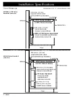
Installation Instructions
Connecting the Gas Line
WARNING
• Before connection, ensure the gas supply meets speci-
fications (Pg. 4).
• Install the included gas regulator before you install/use
the cooktop.
• Ensure the arrow on the regulator points in the direction
of the gas flow (toward the cooktop).
• Do not overtighten the gas connections/fittings.
• Do not use Teflon tape or plumber’s putty on flexible
gas-line connections.
• Before use, test the gas lines for leaks as instructed.
Do not use a flame to check for leaks.
• The gas-supply pressure to the regulator must not
exceed 1/2 psi (pounds per square inch) or 3.5 kPa.
• The cooktop and shut-off valve must be disconnected
from the gas-supply piping system during any pressure
test over 1/2 psi (3.5 kPa).
• You must close the shut-off valve to the cooktop during
any gas-supply piping-system pressure testing equal to
or less than 1/2 psi (3.5 kPa).
• For LP (liquid propane) gas installations, the tank must
have its own high-pressure regulator besides the pres-
sure regulator supplied with the cooktop.
1. Attach the gas-pressure regulator (included) to the
cooktop gas inlet.
(Tight spaces) Install the regulator anywhere between
the cooktop and gas-supply/shut-off valve.
To minimize gas-pressure loss, attach the regulator as
close to the cooktop as possible.
Use a minimum 1/2” flexible gas line (not included) to
connect the regulator to the gas-supply/shut-off valve.
2. Check for gas leaks:
a. Turn OFF all cooktop control valves.
b. With a soap-water solution or gas-leak detector,
check all lines/connections for leaks. (Ensure the
gas-supply/shut-off valve is ON.)
c. Turn the gas supply/shut-off valve OFF.
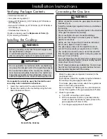
Verifying Package Contents
• Hold-down brackets (2)
• Gas pressure regulator (1)
• Grates: DTCT304G (2), DTCT365G (3) DTCT466G or
HPCT466G (3)
• Burners: DTCT304G (4), DTCT365G (5), DTCT466G or
HPCT466G (6)
• Stainless steel cleaner (1)
If parts are missing, see the
Replacement Parts
(Pg.
12) for ordering information.
Installing the Cooktop
WARNING
• Before proceeding, verify that the power supply meets
the specifications on Page 4.
• To avoid damaging the gas-pressure regulator, install it
after
mounting the cooktop in its permanent position.
IMPORTANT
• Do not overtighten the hold-down bolts; overtightening
may keep the dual gas burners from operating properly.
• Do not seal the cooktop to the counter; the cooktop
must be easily removable for service. The customer is
financially responsible for the added task of removing
sealing compounds in the course of servicing the unit.
If a downdraft vent will be used, first install the vent
according to its installation instructions.
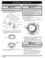
1. Lower the cooktop into the cutout and center it.
2. Secure the cooktop to the countertop using the hold-
down brackets as shown.
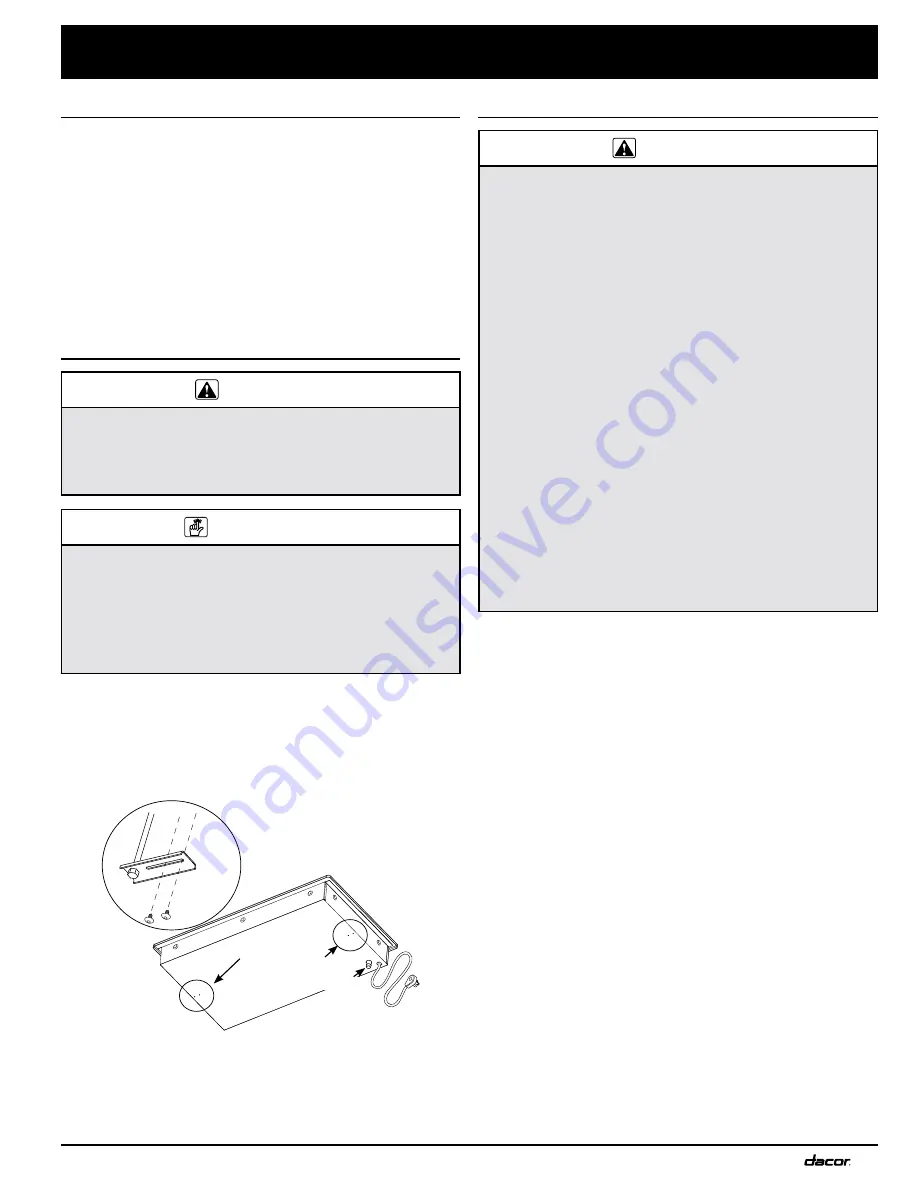
Beneath the Cooktop
Hold-down bracket
mounting holes
Gas inlet
Summary of Contents for Distinctive DTCT365G
Page 18: ...16 Notes...
Page 19: ...17 Notes...


