


11
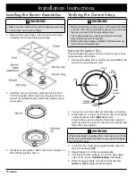
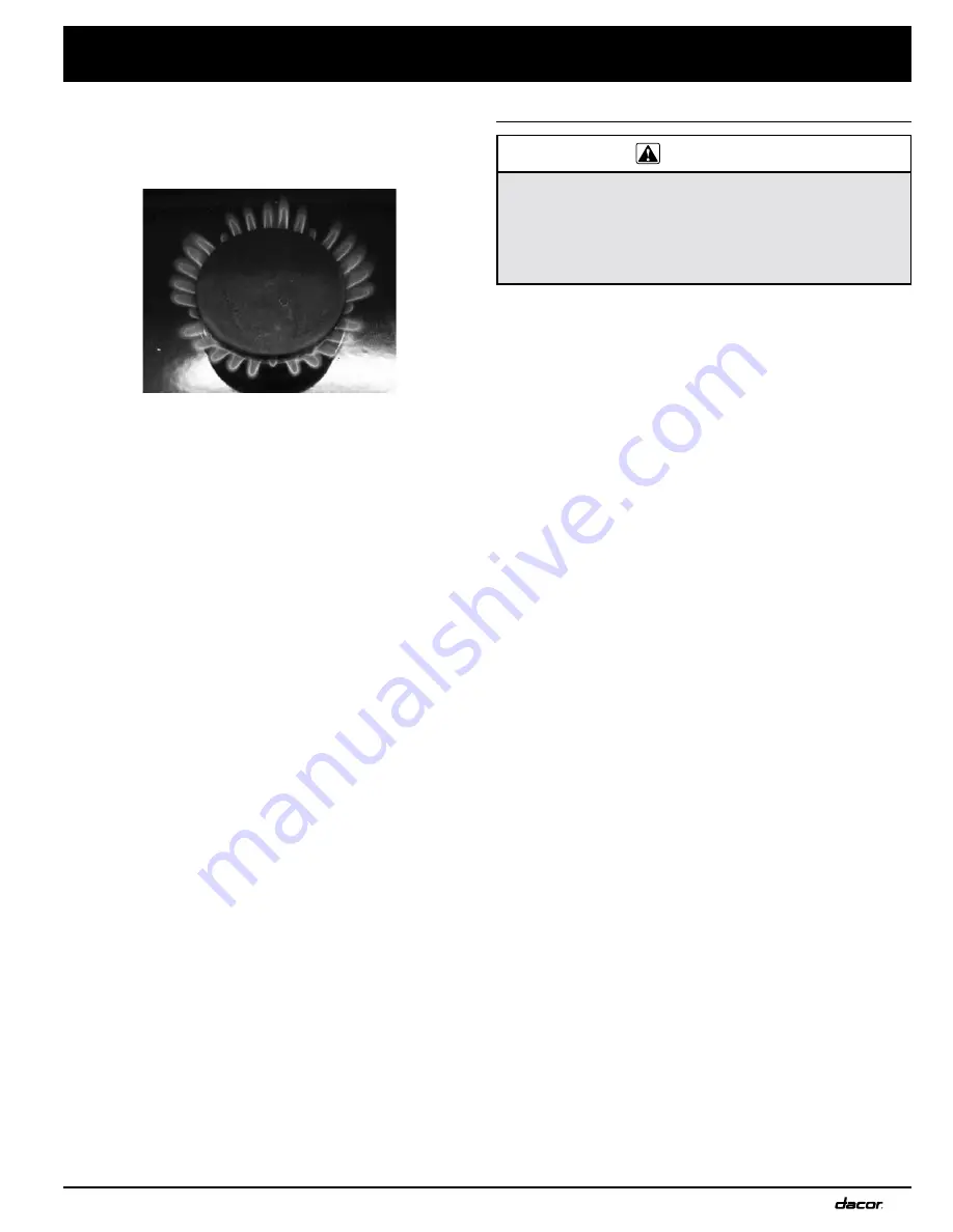
Proper Flame Appearance
• When the unit is installed correctly, the flame burns
steadily and has a sharp, blue inner cone, the length of
which varies with the burner size.
• The flame will be reduced by the Smart Flame™ feature
under the grate fingers to increase grate life.
Troubleshooting—If a Burner Does Not
Function Properly
:
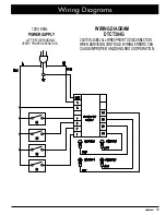
• Verify that power and gas are supplied to the cooktop.
• Verify that the cooktop is plugged in and power is turned
on at the circuit breaker or fuse box.
• Verify that the burners are properly seated.
• If the burner continues to spark after ignition stops, have
a licensed electrician check the electrical outlet for proper
grounding or reversed polarity.
• Re-perform
Running the Ignition Test
(previous page).
• If the appliance still does not work, contact Dacor
Distinctive Service: (800) 793-0093 x2822.
Do not attempt to repair the appliance yourself.
When you call, have the model
and
serial numbers avail-
able. (See the inside cover of this manual for the location
of these numbers.)
Dacor shall not pay to correct problems caused by a
faulty installation.
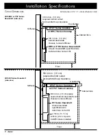
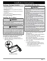
Installation Instructions
Installation Checklist
WARNING
• The installer should complete this checklist to ensure
safe, thorough installation
• The homeowner is responsible for the cooktop’s
proper installation, the importance of which cannot be
overstated.
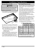
□
The cooktop’s electrical outlet is installed as speci-
fied in this guide and according to applicable electrical
codes (Pg. 4).
□
Gas service to the cooktop is installed as specified in
this guide and according to applicable electrical codes
(Pg. 4).
□
Gas-supply-inlet pressure was measured and falls with-
in the maximums specified in this guide (Pg. 4).
□
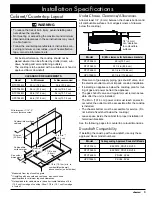
The provided hold-down brackets secure the cooktop
(Pg. 9).
□
The installer connected the cooktop to the gas supply
as instructed in this guide and according to applicable
codes, and verified the gas supply has no leaks (Pg.
9).
□
Burners and grates are properly installed as specified
in this guide (Pg. 10).
□
Proper cooktop function was verified.
□
The warranty was activated (either online or by filling
out and mailing the warranty card).
Summary of Contents for Distinctive DTCT365G
Page 18: ...16 Notes...
Page 19: ...17 Notes...


