background image

English  13

Ins
tallation r

equir

ement

s

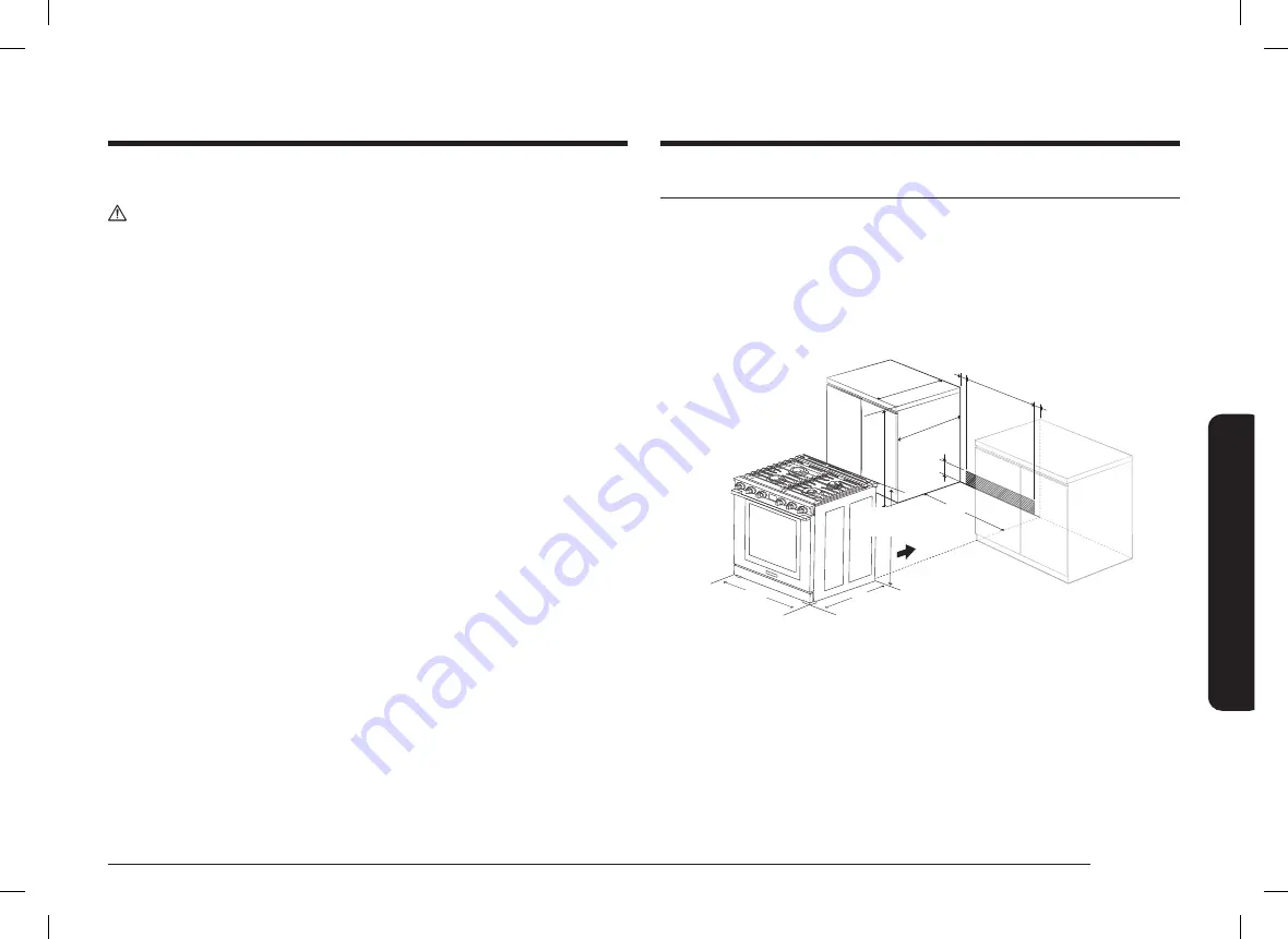
Minimum dimensions

CAUTION

• 

If overhead cabinets are installed, a range hood should also be installed 
and project horizontally a minimum of 5" (12.7 cm) beyond the front of the 
cabinets. Hood is necessary to dissipate any heat buildup in the overhead 
cabinets to prevent possibility of fire, personal injury and/or death. The 
ventilating hood must be constructed of sheet metal not less than 0.0122" 
thick and installed above the cooktop with a clearance of not less than 1/4" 
between the hood and the underside of the combustible material or metal 
cabinet. The hood must be at least as wide as the appliance and centered over 
the appliance. Clearance between the cooking surface and the ventilation hood 
surface must never be less than 24".

• 

Exception 1 

: Installation of a listed microwave oven or cooking appliance 

over the cooktop shall conform to the installation manual provided with the 
appliance.


-

30" (76.2 cm) minimum clearance between the top of the cooking 
surface and the bottom of an unprotected wood or metal cabinet; or If 
30" (76.2 cm) clearance is not possible, minimum of 24" (61 cm) can be 
used when the bottom of the wood or metal cabinet is protected by not 
less than 1/4" (0.64 cm) flame-retardant millboard covered with not less 
than no. 28 MSG sheet steel, 0.015" (0.038 cm) stainless steel, 0.024" 
(0.061 cm) aluminum, or 0.020" (0.051 cm) copper.


-

18" (45.7 cm) of minimum clearance between the countertop and the 
adjacent cabinet bottom.

• 

Exception 2

 : For island installation, maintain 21/2" minimum from cutout 

to back edge of countertop and 4" minimum from cutout to side edges of 
countertop.

Installation guide

IMPORTANT:

To eliminate the risk of burns or fire caused by reaching over heated surface units, 
avoid having cabinet storage space located above the surface units. If you have cabinet 
storage space over the heating elements, you can reduce the risk by installing a range 
hood that projects horizontally a minimum of 5 inches beyond the bottom of the 
cabinets.

Installation guide

A: Cabinet opening 

30” (76.2)

IMPORTANT: 

If your cabinet have height over 37”, this range cannot be installed 

without supporting unit like hard block.

3"

24"

24"

A

25"

29 

15

/

16

"

(761.0 mm)

26 

7

/

16

"

(671.7 mm)

36 

1

/

4

"-37

(921.2 mm)

3"

INSTALL_DOP30T840GS_DA_DG68-01456A-00_EN.indd   13

INSTALL_DOP30T840GS_DA_DG68-01456A-00_EN.indd   13

2022-10-06   오후 6:51:56

2022-10-06   오후 6:51:56

Summary of Contents for DOP30 40G Series

Page 1: ...Installation manual Gas Pro Range DOP30 40G INSTALL_DOP30T840GS_DA_DG68 01456A 00_EN indd 1 INSTALL_DOP30T840GS_DA_DG68 01456A 00_EN indd 1 2022 10 06 6 51 54 2022 10 06 6 51 54...

Page 2: ...step sit lean on the door or drawer to prevent accidental tipping of the range WARNING If the information in this manual is not followed exactly a fire or explosion may result causing property damage...

Page 3: ...safety 10 Storage drawer safety 10 Gas range components 11 Gas range specifications 11 Installation requirements 12 Location requirements 12 Installation guide 13 To remove safely from the pallet 15 T...

Page 4: ...llation instructions before installing the range Remove all packing materials from the oven compartments before connecting the electric and gas supply to the range Observe all governing codes and ordi...

Page 5: ...r gas fitter qualified or licensed by the State of Massachusetts When using ball type gas shut off valves you must use the T handle type Multiple flexible gas lines must not be connected in series Gen...

Page 6: ...he risk of fire electric shock personal injuries and or death obey the following precautions Do not store place or use flammable or combustible materials such as charcoal paper plastic pot holders lin...

Page 7: ...ical and grounding safety WARNING To reduce the risk of fire electric shock personal injuries and or death obey the following precautions Plug into a grounded 3 prong outlet Do not remove the ground p...

Page 8: ...an cookware on the cooktop Make sure your range is correctly installed and adjusted by a qualified service technician or installer for the type of gas natural or LP you will use For your range to util...

Page 9: ...ts of the burner for cleaning make sure the range is off and completely cool After cleaning the burner spreader make sure it is completely dry before re assembling Make sure the spark mark on the dual...

Page 10: ...rawer into the oven cavity when you run a self cleaning cycle When opening the door after a self cleaning cycle stand away from the oven If the self cleaning cycle malfunctions turn off the oven disco...

Page 11: ...0 BTU Surface burners LP LF 15 000 BTU LR 15 000 BTU RF 17 500 BTU RR 9 500 BTU Oven burners NG Broil Upper 16 500 BTU Bake Lower 18 000 BTU Oven burners LP Broil Upper 14 500 BTU Bake Lower 15 000 BT...

Page 12: ...arances Do not locate the range where it may be subject to strong drafts Provide adequate clearances between the range and adjacent combustible surfaces These dimensions must be met for safe use of th...

Page 13: ...ce is not possible minimum of 24 61 cm can be used when the bottom of the wood or metal cabinet is protected by not less than 1 4 0 64 cm flame retardant millboard covered with not less than no 28 MSG...

Page 14: ...it to install the range in a freestanding cutout cabinet For more information see Optional rear filler kit as shown below Optional rear filler kit WARNING Used to fill gap between the range back and w...

Page 15: ...the pallet Use caution not to hold the door handle To avoid breakage CAUTION Please DO NOT push the unit strongly when you install These actions can cause the damage to the unit Hold the upper left r...

Page 16: ...gas for which it is designed Do not attempt to convert the appliance from the gas specified in this manual to a different gas without consulting the gas supplier This range is convertible for use on n...

Page 17: ...tlet have a proper outlet installed by a qualified electrician All wiring and grounding must be done in accordance with local codes or in the absence of local codes with the National Electrical Code A...

Page 18: ...e near the bottom left corner The 53 in 135 cm power cord will come installed on the range and taped to the back for shipping Grounding Ensure proper ground and firm connection before use All ranges m...

Page 19: ...of the supplied parts contact your local retailer Parts needed Gas line shut off valve Flexible metal appliance connector ID x 5 ft Flare union adapter or NPT x ID Flare union adapter NPT x ID 135 de...

Page 20: ...other gas appliances when you turn the gas back on Because hard piping restricts movement of the range the use of a CSA International certified flexible metal appliance connector is recommended unless...

Page 21: ...oints and connections to check for leaks in the system WARNING Do not use a flame to check for gas leaks to prevent death personal injury explosion and or fire hazard When using test pressures greater...

Page 22: ...WARNING To reduce the risk of tipping the appliance must be secured by properly installing the anti tip device packed with the appliance All ranges can tip resulting in personal injury Tipping ranges...

Page 23: ...BEFORE OPERATING OR TESTING follow the grounding requirements on pages 17 18 in this manual Improper connection of the grounding plug can result in a risk of electric shock All gas ranges come with a...

Page 24: ...he cooktop without the surface burner grates is level with the countertops 4 Position an oven rack in the center rack position 5 Check the level of the range with a carpenter level using the two posit...

Page 25: ...working properly The burner will light in about 4 seconds after the air has been purged from the supply line 2 After the burner lights turn the control knob to the desired setting The clicking sound w...

Page 26: ...for service Normal burner flames shall look like 1 or 2 depending on the gas type you use Step 9 Final installation checklist You have just completed installing your range Make sure all controls are...

Page 27: ...the oven door 2 Remove the oven racks 3 Remove the oven floor 4 Turn the mode selector knob from OFF to the Bake position and then rotate the temperature selector knob to set the temperature from the...

Page 28: ...the burner ports gradually reduce the air shutter opening until the flames are stabilized If flames are too yellow and or too large gradually increase the air shutter opening until the flames have ap...

Page 29: ...Make sure the screwdriver flathead is seated into the set screw groove 3 Rotate valve set screw clockwise to decrease LO setting flame output or rotate set screw counter clockwise to increase LO sett...

Page 30: ...Memo Memo INSTALL_DOP30T840GS_DA_DG68 01456A 00_EN indd 30 INSTALL_DOP30T840GS_DA_DG68 01456A 00_EN indd 30 2022 10 06 6 52 01 2022 10 06 6 52 01...

Page 31: ...ealer Showroom H Another Dacor Owner D Kitchen Dealer Showroom I Model Home E Home Show J Other 2 Where did you buy your Dacor appliances A Appliance Dealer D Builder B Kitchen Dealer E Other C Builde...

Page 32: ...Industry CA 91745 Phone 833 35 ELITE 833 353 5483 Fax 626 403 3130 www dacor com DG68 01456A 00 INSTALL_DOP30T840GS_DA_DG68 01456A 00_EN indd 32 INSTALL_DOP30T840GS_DA_DG68 01456A 00_EN indd 32 2022...

Reviews: