English
36
Installation instructions
Installation instructions
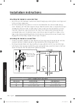
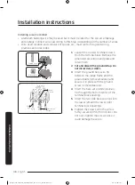
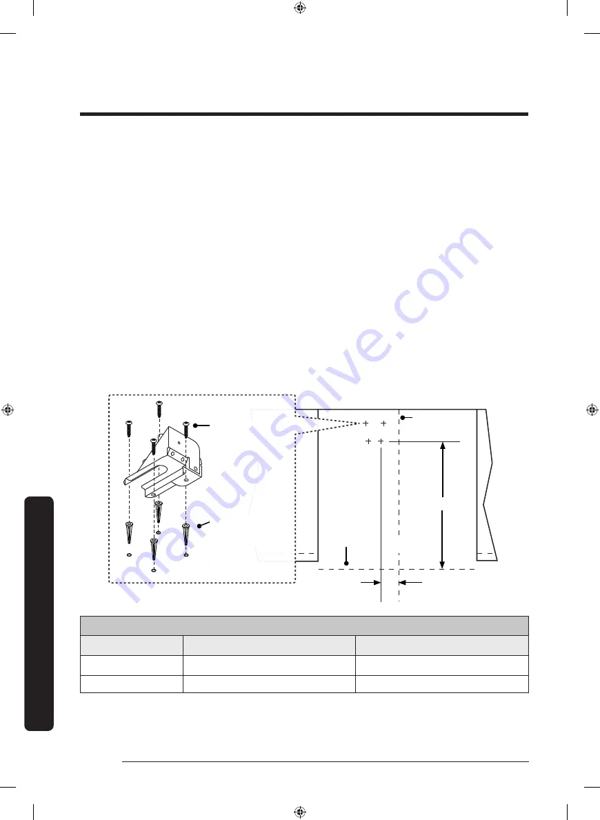
Attaching the bracket to a concrete floor:
• Drill four (4) 3/8” diameter countersink holes through any existing floor covering down
to the concrete slab below.
• Drill the 4 holes for the anchors 1 1/4” (3.2 cm) deep into the concrete slab using a
3/16” masonry bit. This hole length is longer than the anchor, but is required for proper
installation. Clear the holes of dust and any other material. Tap each anchor into the
hole until the anchor top is flush with the top of the concrete slab. Position the anti-
tip bracket holes over the anchor holes. Insert the screws through the 4 holes in the
base of the bracket and thread them into the anchors. Be sure the screw threads fully
engage the anchor body. Tighten the screws into place.
Attaching the bracket to a wood floor:
• If there is ceramic, asphalt or other hard floor covering over the wood below, drill (4)
countersink holes to allow access to the wood below for drilling pilot holes.
• Drill four (4) pilot holes into the wood floor using a drill bit (1/16” dia. for #8 screws,
1/8” dia. for #12 screws). Position the anti-tip bracket holes over the holes in the floor.
Insert the screws into the wood and tighten into place.
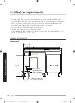
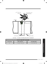
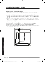
C
B
A
TOP VIEW
Range center line
#8 x 1” #8 x 1 1/4”
or #12 x 1 3/4 screw,
4 places (see text)
Anchor, 4 places:
use for concrete
floor only
Range
front panel
ANTI-TIP BRACKET PLACEMENT
Dimension
DOP36M94DL*
DOP48M96DL*
A
13” (33.0 cm)
3 1/2” (8.9 cm)
B
22 1/2” (57.2 cm)
22 1/2” (57.2 cm)
Install_NY9900M_PRORANGE_DOP48M96DLM_DA_DG68-00936A-00_EN+MES+CFR.indb 36
2017-05-12 7:36:48

