background image

6

Cabinet/Countertop Dimensions (cont.)

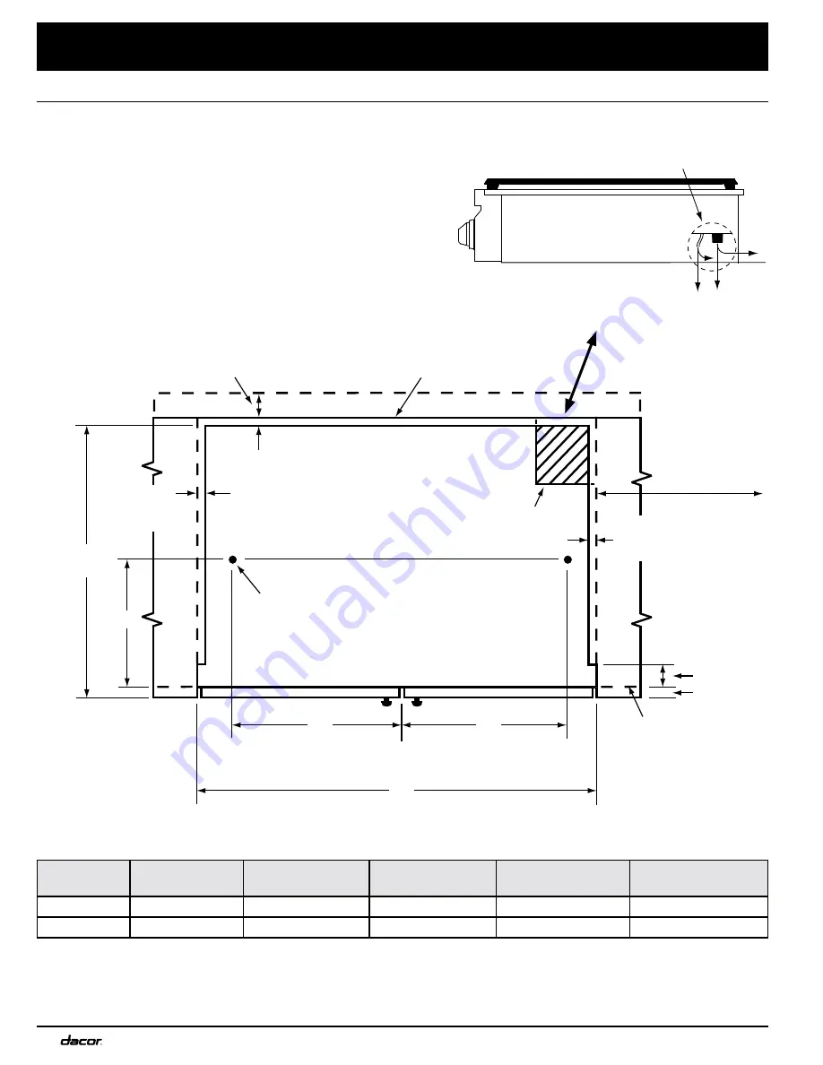
Installation Requirements

Cutout tole1/16” -0 (+1.6 mm, 0) unless otherwise noted.

Non-combustible 

rear wall, rear of 

mounting platform

10” (25.4 cm) min. 

to combustible wall 

above countertop, 

both sides

Cabinet face 

below countertop 

overhang

Increase countertop and overhang  

additional 2 1/2” (6.4 cm) min. for 

combustible rear wall  above 

countertop

3/8” (1.3 cm) 

countertop overhang

Hole 1/2” dia. (1.3 cm), 

2 places, through platform

for hold down bolts 

Gas/electrical utility cut-out in right rear corner of 

mounting platform 8” W X 6” D (20.3 cm X 15.2 cm),

if gas and electrical are routed through bottom

1/2” (1.3 cm) 

countertop 

overhang

1” thick mounting platform min.

Countertop

Countertop

1/2” (1.3 cm) 

countertop 

overhang

2” (5.1 cm)
1” (2.5 cm)

E

24 5/8” 

(62.5 cm)

D

D

B

CL

Cooktop 

Model

B - Cutout 

Width

D

E

F - Raised Vent 

Cutout

Approved Raised 

Vent Models

DRT304S

30” (76.2 cm)

13 3/8” (34.0 cm)

10 1/8” (25.7 cm)

NA

None*

DRT366S

36” (91.4 cm)

16 5/8” (42.2 cm)

11 3/16” (28.4 cm)

33 1/2” (85.1 cm)

ERV3615**

*  


Model DRT304 is not approved for use with a raised vent. 

** Use only raised vent model specified. Raised vent is not compatible with DRT cooktops having a serial number starting 

with letters “SA.”

Cabinet/Countertop Cutout Dimensions Without Raised Vent- Top View

Gas connection and power cord may be 

routed through bottom or back of chassis

Gas and electrical connections at 

right rear section of chassis

Summary of Contents for DRT304

Page 1: ...ion Instructions Distinctive Series Cooktop Models DRT304S DRT366S Part No 106522 Rev E THIS APPLIANCE HAS BEEN TESTED IN ACCORDANCE WITH THE LATEST EDITION OF ANSI Z21 1 STANDARD FOR HOUSEHOLD GAS AP...

Page 2: ...uilding inspector s use 2009 Dacor all rights reserved If You Need Help If you have questions or problems with installation contact your Dacor dealer or the Dacor Customer Service Team For repairs to...

Page 3: ...ANT If you smell gas Do not use or light any appliance Do not touch any electrical switch or use any electri cal devices including the telephone in your building From a neighbor s phone immediately ca...

Page 4: ...anying it This cooktop is not intended for commer cial or laboratory use DO NOT TOUCH THE SURFACES OF THE COOKTOP OR THE SURROUNDING AREAS DURING OR IMMEDIATELY AFTER USE WARNING General Safety Precau...

Page 5: ...should be installed in accordance with the National Fuel Gas Code ANSI Z223 1 NFPA 54 The gas service must be installed by a qualified profes sional Be certain that the cooktop being installed is cor...

Page 6: ...evel The countertop overhang on the sides of the cutout shown on the following pages covers the recessed por tions of the cooktop behind the control panel and cre ates a seamless look for the installa...

Page 7: ...noted Continued on following pages See note 2 2 See Cabinet Countertop Dimensions Top View 3 Not applicable for cabinets more than a horizontal distance of 10 25 4 cm from the edge of the cooktop 1 Ve...

Page 8: ...l are routed through bottom 1 2 1 3 cm countertop overhang 1 thick mounting platform min Countertop Countertop 1 2 1 3 cm countertop overhang 2 5 1 cm 1 2 5 cm E 24 5 8 62 5 cm D D B C L Cooktop Model...

Page 9: ...low to allow for raised vent gas and electrical connections Countertop Countertop 1 2 1 3 cm countertop overhang 2 5 1 cm 1 2 5 cm 15 38 1 cm 24 1 2 62 2 cm D E D F B C L Stiffener Cabinet face Contro...

Page 10: ...DRT366S Knobs standard PN 106575 04 3 4 Knobs SimmerSear PN 106575 05 1 2 10 inch grate PN 700037 none 1 12 inch grate PN 701196 none 2 14 inch grate PN 101524 2 none Standard burner cap small PN 102...

Page 11: ...h the cooktop Knob Installation 1 Attach the SimmerSear burner knobs A as shown below The SimmerSear knobs have a wider space between the large flame icon and the simmer icon than the standard burner...

Page 12: ...indentations on the bottom of the burner ring with the pins on the top of the burner base 2 Set the outer SimmerSear burner cap s on top of the burner ring s Make sure the burner ring is centered on t...

Page 13: ...e power plug is connected to the electrical outlet and that power is turned on at the circuit breaker or fuse box Check to make sure that all burner parts are properly seated If the burner continues t...

Page 14: ...TOR RL FL FR RR B W B FL INDICATOR LIGHT W B W B W B B W W W W Single Point Spark Module Single Point Spark Module Single Point Spark Module Single Point Spark Module 120V 60Hz 0 25A POWER SUPPLY WIRI...

Page 15: ...T FR INDICATOR LIGHT B B W W W B B B RC INDICATOR LIGHT B W RR INDICATOR LIGHT B W RR RC FC FR RL FL B B Single Point Spark Module W W Single Point Spark Module Single Point Spark Module Single Point...

Page 16: ...Dacor 600 Anton Blvd Suite 1000 Costa Mesa CA 92626 Phone 800 793 0093 Fax 626 403 3130 www Dacor com...

Reviews: