background image

Summary of Contents for ER30D

Page 1: ...or use with models ER3OD ER3OD C ER3ODSR Installation Instructions THIS APPLIANCE HAS BEEN TESTED IN ACCORDANCE WITH THE LATEST EDITION OF ANSI Z21 1 STANDARD FOR HOUSEHOLD GAS COOKING APPLIANCES Part No 102187 Rev J ...

Page 2: ...All specifications subject to change without notice Dacor assumes no liability for changes to specifications 2007 Dacor all rights reserved ...

Page 3: ...ll the gas supplier Follow the gas suppher s instructions If you cannot contact the gas supplier call the fire department IMPORTANT Do not store or use combusttble flammable or explosive vapors and liquids such as gasoline inside or in the vicinity of this or any other appliance Also keep items that could explode such as aerosol cans away from the burners and the oven Do not store flammable or exp...

Page 4: ...ot allow children to play with the controls pull on the handle or touch other parts of the range Do not store items of interest to children on top of or above the range Children could be burned or injured while climbing on the appliance Do not attempt to use this appliance in the event of a power failure Do not tamper with the controls Do not adjust or alter any part of the range unless specifical...

Page 5: ...contact your Dacor dealer ortheDacor Customer Service Team Forrepairs toDacor appliances under warranty calltheDacor Distinctive Service line Whenever youcall have themodel andserial number oftheappliance ready Theserial number andrating labels canbeseen through thegrillbelow thecontrol panel on theright side Dacor Customer Service Phone 800 793 0093 U S A and Canada Monday Friday 6 00 A M to 8 00...

Page 6: ... electrical receptacle according to the type of wiring used 4 _acar Electrical Requirements Freestanding Units for Use in Canada It is the owner s responsibility to ensure that the required 4 wire electrical outlet is installed by a licensed electrician as specified below prior to range installation The electrical outlet installation including minimum supply wire size and grounding must be in acco...

Page 7: ... All Models i 1 9 16 _ 40 mm t _ Width at front panel 29 7 8 758 mm 46 1 4 1175 mm l J I E i 28 13116 732 mm _ 27 5 16 694 mm _ 26 5 16 668 mm _ 24 1 4 616 mm _ 1 1 16 27 mm _ t 9 229 mm Backguard 1 1 16 27 mm to cooking surface top of grates from top of trim Finished side panel Front of open door Front of handle Front edge of bullnose Front panel Rear of front panel oven door 6 152 mm 3 76 mm Bac...

Page 8: ...t of open door Front of handle Front edge of bullnose Front panel Rear of front panel oven door Rear of front panel to back of chassis 35 3 4 908 mm to 37 7 8 962 mm Self Rimming Model ER30DSR with Standard Trim i I I Width at front panel 29 7 8 758 mm 46 1 8 1172 mm _ 28 11 16 729 mm _ _ 27 3 16 691 mm 26 3 16 665 mm _ 24 1 8 613 mm _ _ 231 8 567 mm _ J _ 1_ 16 33mm tocooking surface top of grate...

Page 9: ...ng codes for permissible gas valve locations An external manual shut off valve must be installed between the gas inlet and the range for the purpose of turning on or shutting off gas to the appliance The installation must allow for the following Access to the gas shut off valve when the unit is installed Access to the remote circuit breaker panel or fuse box when the range is in place The gas supp...

Page 10: ...e side _ I wall above range _ I Cabinet face I _ I __ _ __ ___ _ __ Notchcountertop overhang to width of cabinets Countertop front Countertop Height Min 35 5 8 905 mm Max 37 1 4 946 mm Top View Model ER30DSR Counter Cabinet Cutout Dimensions Self Rimming Installation with Raised Vent ER30DSR with H J K no side panels no 23 1 2 23 1 2 24 to raised vent 597 mm 597 mm 25 9 16 3 inch side panels 20 1 ...

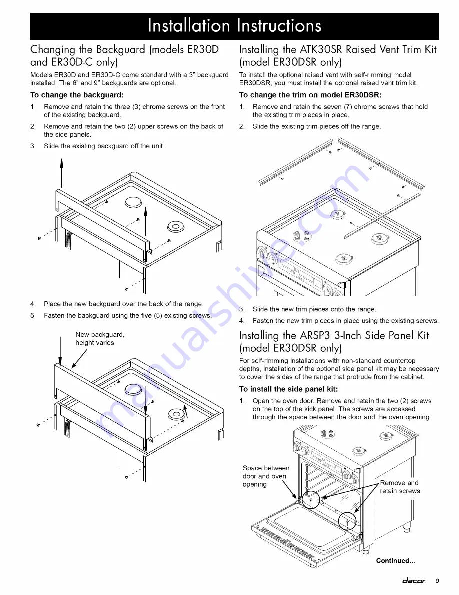
Page 11: ...ld the existing trim pieces in place 2 Slide the existing trim pieces off the range 4 Place the new backguard over the back of the range 5 Fasten the backguard using the five 5 existing screws New backguard height varies 3 Slide the new trim pieces onto the range 4 Fasten the new trim pieces in place using the existing screws Installing the ARSP3 3 Inch Side Panel Kit model ER3ODSRonly For self ri...

Page 12: ...9 inserts through a hole in the front panel to attach the bottom of the side panel 3 Kick panel Remove and retain screw both sides Remove the left end cap retaining screw from under the rim of the control panel and remove the end cap Hex screw Side panel Hex screw Hex screw Torx screw Front panel 7 Reinstall the end cap 4 Hold the left side panel in position on the side of the range Locate the cen...

Page 13: ...ust the Range Height Raise or lower the range to prepare for final installation For model ER30D and ER30D C adjust the height until the top edge of the trim around the edge of the of the cooktop is slightly higher than the countertop For model ER30DSR raise the range until the bottom edge of the trim around the edge of the of the cooktop is 118 higher than the countertop Rear leg Back of range 2 1...

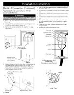
Page 14: ...m the oven while continuing to lift 12 _acar Door Gripping Points NOTE Freestanding model ER30D C is wired for use in Canada and comes from the factory pre wired If installing a pre wired range skip to Gas Supply Connection on page 17 Put slack in electrical wiring and gas line IMPORTANT Make sure that the conduit or appliance cord is tong enough to allow the range to be pulled out for service wit...

Page 15: ...end of the strain relief into the hole on the bottom of the range electrical box 5 Before connecting the wires slide the strain relief nut over the wires and thread it onto the conduit strain relief inside the box Tighten into place 6 Connect the white wire to the neutral terminal in the box 7 Connect the black wire to the L1 power supply terminal 8 Connect the red wire to the L2 power supply term...

Page 16: ...lack L1 power supply wire in the junction box 4 Connect the red wire from the appliance to the red L2 power supply wire in the junction box 5 If using a 4 wire connection connect the green wire to a grounded supply wire in the junction box or to a grounded cold water pipe If connecting to a grounded cold water pipe 0 Use a separate copper grounding wire No 10 minimum to connect to the cold water p...

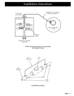
Page 17: ...arate No 10 minimum copper grounding wire Wire nut 4 places Connection to appliance Page 13 4 Wire Conduit Connection to Junction Box with External Ground Metal water pipe No 4 copper wire Meter Clamps Bare metal Insulated Pipe Jumper _ _acar 15 ...

Page 18: ... box and the strain relief itself is inside the box Strain relief 5 6 7 8 9 Slide the end of the appliance cord into the strain relief from the bottom of the box Connect the white neutral wire to the neutral terminal in the box Connect the L1 wire to the L1 power supply terminal in the box Connect the L2 wire to the L2 power supply terminal in the box If using a 4 wire connection connect the groun...

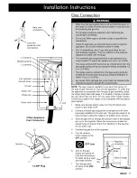
Page 19: ...he type of gas supplied 1 Make sure the gas supply valve is in the off position and power to the range is off 2 Connect a flexible gas supply line to the gas shut off valve previously installed on the stub out The gas line needs to be long enough to allow the range to be pulled out for service 3 Slide the gas line up through the access holes in the chassis and up to the regulator Move the wires ar...

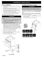
Page 20: ...f the valve shaft Carefully push the knob on until it stops Put the knobs with the words MAX GRIDDLE on them onto the right valve shafts Put the remaining knobs on the left valve shafts 1 Grasp the oven door on opposite sides and hold it at a 15 angle from the front of the oven Slide the hinges into the hinge openings resting the bottom of the hinge arms on the hinge receptacles Continue to hold t...

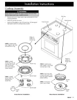
Page 21: ...ll burner ring Line up ring tabs with head slots Twist back and forth to assure proper seating Ridge on bottom of burner cap Burner ring STEP 3 Install burner caps Ridge on cap must surround top of ring Ridge on bottom of burner cap STEP 1 Install burner head Put locating tab in keyed hole eyed hole Burner head Burner base STEP 2 Turn ring until it drops into place Twist f_ bpa ka nde _ti_hg t ass...

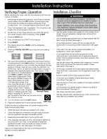
Page 22: ... not operate properly follow these troubleshooting steps 1 Verify that power and gas are supplied to the range 2 Check the electrical connections and gas supply to ensure that the installation has been completed correctly 3 Repeat the above bake test or burner ignition test 4 If the appliance still does not work contact Dacor Distinctive Service at 877 337 3226 Do not attempt to repair the applian...

Page 23: ... Family Owned American Made Dacor 600 Anton Blvd Suite 1000 Costa Mesa CA 92626 Phone 800 793 0093 Fax 626 403 3130 www Dacor com The Life of the Kitchen ...

Reviews: