background image

9

Installation Specifications

Calculating the Maximum Duct Run Length

• 

For optimal performance, consult a qualified HVAC 

specialist when designing the duct system. 

• 

Do not use duct work that is smaller in cross-sectional 

area than the required duct sizes in the tables below.

• 

Keep the duct run as short as possible for best perfor-

mance and never exceed the maximums stated in the 

table below right.

• 

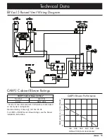
The maximum duct length for the raised vent system 

depends on the blower model used and the number 

of elbows and transitions. The

 Equivalent Number of 

Feet

 for each elbow and transition (see table below) 

must be subtracted from the maximum straight length 

to compensate for wind resistance. To determine the 

maximum allowable length of the duct work, subtract all 

of the equivalent lengths of the elbows and transitions 

listed below from the 

Blower Maximum Duct Straight 

Length

 (see table right).

For example, for a raised vent system using 3 ¼” X 

10” rectangular duct, two (2) 3 ¼” x 10” 90° elbows, a 

3 ¼” X 10” rectangular to 10” round transition, and a 

REMP16 remote blower:

• 

From the 

Blower Maximum Duct Straight Length


table below, the maximum length without transitions 

and elbows is 60 feet.

• 

The equivalent length of each 90

°

 elbow is 15 feet.

• 

The equivalent length of 45

°

 elbow is 2 feet.

• 

The equivalent length of the transition is 4 feet.

• 

The total equivalent length of the above components is: 

15 feet + 15 feet + 4 feet + 2 feet = 36 feet.

• 

The maximum amount of straight duct that can be used 

with a REMP16 and the above components is: 60 feet - 

34 feet = 24 feet.

Equivalent Number of Feet (Nominal) - 

Duct Elbows and Transitions

45° elbow 

8 inch

3 feet

3 ¼” x 10” 

45° elbow

7 feet

45° elbow

10 inch

2 feet

3 ¼” x 10” 

90° elbow

15 feet

90° elbow 

8 inch

7 feet

3 ¼” x 10” 

90° flat elbow

20 feet

90° elbow

10 inch

5 feet

3 ¼” x 10”  

to 8” round 

transition

4 feet

90° 3 ¼” x 10” 

to 8” round

transition

25 feet

3 ¼” x 10”  

to 10” round 

transition

4 feet

Roof cap

*

Wall cap**

*

* The equivalent lengths of roof and wall caps vary with 

model and configuration. For equivalent length, contact the 

manufacturer or a qualified HVAC specialist.
** Not applicable for REMP series blowers.

Duct Work Design Tips

• 

Wherever possible, reduce the number of transitions 

and turns to as few sharp angles as possible. Two 

staggered 45° angles are better than one 90°. Keep 

turns as far away from the hood exhaust as possible, 

with as much space between each bend as possible.

• 

For best performance, use round duct instead of rect-

angular when possible, especially when elbows are 

required.

• 

If multiple elbows are used, try to keep a minimum of 

24” of straight duct between them. Avoid “S” or “back to 

back” configurations of adjacent elbows.

• 

Do not use flexible metal duct.
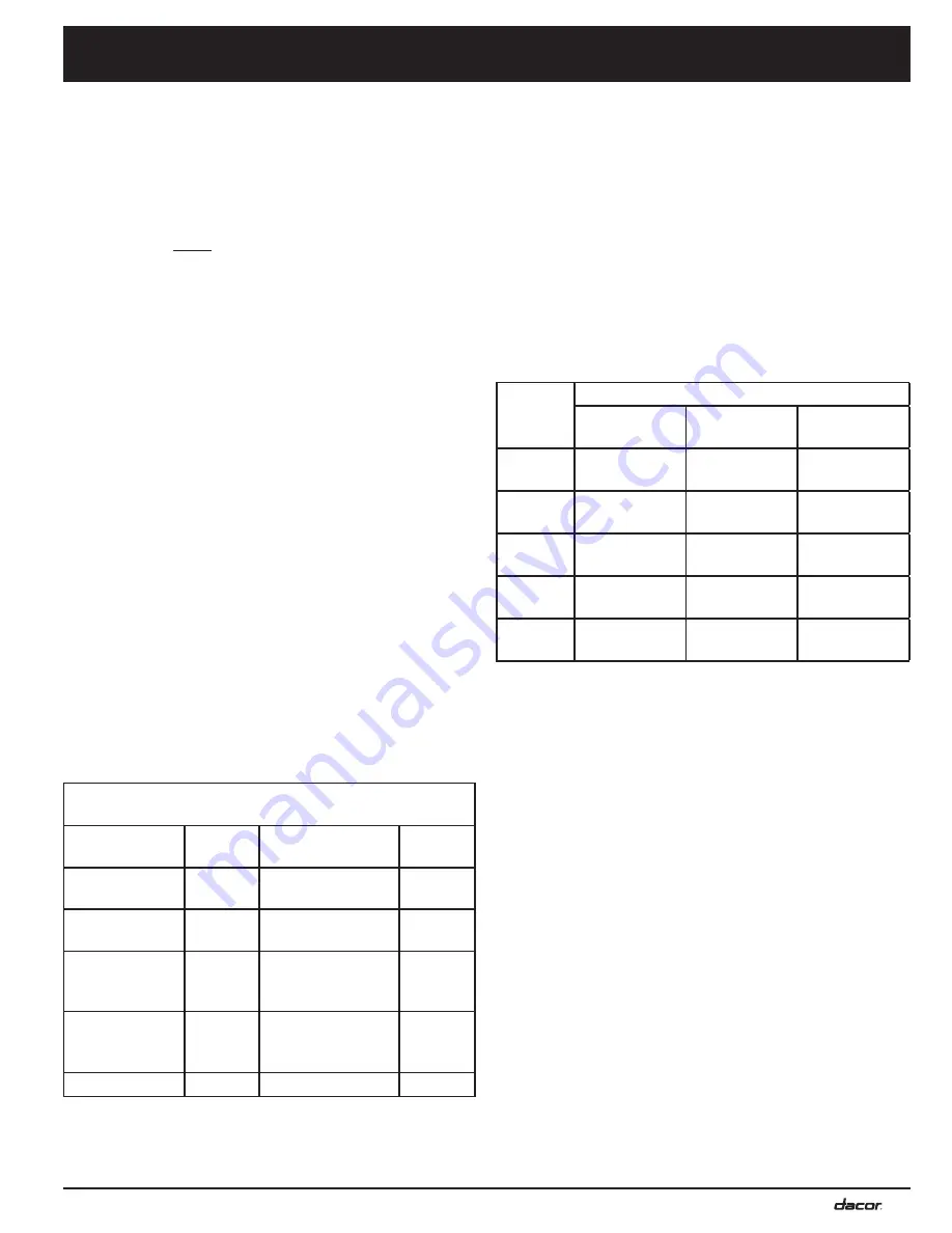
Blower 

Used

Blower Maximum Duct Straight Length

8 Inch Duct

10 Inch Duct

3 ¼” x 10” 

Duct

CABP3

40 feet  

(12.2 m)

30 feet 

(9.2 m)

30 feet 

(9.2 m)

ILHSF8

50 feet 

(15.2 m)

40 feet 

(12.2 m)

40 feet 

(12.2 m)

ILHSF10

60 feet 

(18.3 m)

70 feet 

(21.3 m)

60 feet 

(18.3 m)

REMP3

50 feet 

(15.2 m)

40 feet 

(12.2 m)

40 feet 

(12.2 m)

REMP16

60 feet 

(18.3 m)

70 feet 

(21.3 m)

60 feet 

(18.3 m)

Summary of Contents for ERV3015

Page 1: ...rt No 107000 Rev D Use these downdraft raised vents only with approved Dacor appliances See the installation instructions for the particular appliance model being installed to determine suitability Includes installation instructions for optional cabinet blower Dacor model CABP3 ...

Page 2: ...ad these installation instructions completely and care fully before you begin the installation process Leave these installation instructions with the customer Customer Keep these installation instructions for future reference and the local electrical inspector s use 2011 Dacor all rights reserved If You Need Help If you have questions or problems with installation contact your Dacor dealer or the ...

Page 3: ...rom the power cord Use an adapter plug Use an extension cord Use a power cord that is frayed or damaged Use of a ground fault interrupter GFI is not recommended DANGER IMPORTANT Do not store or use combustible flammable or explosive vapors and liquids such as gasoline inside or in the vicinity of this or any other appliance Also keep items that could explode such as aerosol cans away from the rang...

Page 4: ... not tamper with the controls Never allow the filters or vent openings to become blocked or clogged Do not allow foreign objects such as cigarettes or napkins to be sucked into the vent holes Clean the filters and all grease laden surfaces often to prevent grease fires and maintain performance Clean this appliance only as specified in the use and care manual Do not leave children or pets alone or ...

Page 5: ...6 cm Adjustable anchor legs Product data label Tolerances 1 16 1 6 mm unless otherwise stated Model Number A Top Cap Width B Chassis Width ERV3015 30 76 2 cm 27 3 8 69 5 cm ERV3615 36 91 4 cm 33 3 8 84 8 cm See page 7 and 8 for exhaust locations and dimensions Maximum height of raised vent must not exceed maximum specified counter height for cooking appliance See installation instructions for cook...

Page 6: ...ical gas supplies of both appliances must be provided for inspection and service Any drawers or shelves must be easy to remove for access to the cooktop raised vent and utilities There are 7 8 access holes in the bottom and side of the raised vent for connecting the blower wiring and strain relief Wire the blower to turn on when the raised vent is turned on When installing a remote or in line blow...

Page 7: ...rear exhaust Floor Wiring conduit from raised vent to remote blower CABP3 cabinet blower Cooktop Floor 12 min 30 5 cm 3 1 4 x 10 90 elbow Wall Raised vent Wall cap Backsplash ILHSF series in line blower 3 x 10 to round transition Duct work Duct work Outside wall Range Wall cap on outside wall exahust Raised vent Raised vent configured for bottom exhaust Floor Wiring conduit from raised vent to in ...

Page 8: ... RISK OF FIRE USE ONLY METAL DUCT WORK DO NOT install more than one blower to increase the length of the duct run Even small differences between blower air flow rates can greatly reduce the air draw by the raised vent You must install one of the Dacor blower models listed below for the raised vent to operate properly See the blow er installation instructions for directions For model CABP3 see the ...

Page 9: ...knock out lines up with vertical center line of chassis On 30 and 36 wide models the vertical center line of bottom knock out is offset 3 Side exhaust knock outs 1 5 8 x 16 Bottom exhaust knock out 1 5 8 x 16 Motor cover Front of unit 26 66 0 cm 6 1 4 15 9 cm 1 1 8 2 9 cm C L C L C L Exhaust Knock out Locations for Use with REMP and ILHSF Series Blowers Use sheet metal screws as required to suppor...

Page 10: ... center line Countertop 3 1 4 x 10 duct connection Duct connection center line B Raised vent center line Countertop 3 1 4 x 10 duct connection 15 3 8 39 1 cm Duct connection center line A Raised vent center line Countertop 3 1 4 x 10 duct connection 26 1 4 66 7 cm Exhaust Locations and Side Dimensions for CABP3 Cabinet blower Exhaust Locations and Dimensions for CABP3 Cabinet Blower Installations ...

Page 11: ...feet 36 feet The maximum amount of straight duct that can be used with a REMP16 and the above components is 60 feet 34 feet 24 feet Equivalent Number of Feet Nominal Duct Elbows and Transitions 45 elbow 8 inch 3 feet 3 x 10 45 elbow 7 feet 45 elbow 10 inch 2 feet 3 x 10 90 elbow 15 feet 90 elbow 8 inch 7 feet 3 x 10 90 flat elbow 20 feet 90 elbow 10 inch 5 feet 3 x 10 to 8 round transition 4 feet ...

Page 12: ...ack of the cutout separate from the range or cooktop Install the raised vent before installing the range or cooktop 2 Start by loosely attaching the anchoring legs to the studs on the left and right sides of the raised vent using the provided keps nuts and washers Installation Preparation for Raised Vent with ILHSF or REMP Series Blower NOTE For units using the CABP3 cabinet blower skip to Install...

Page 13: ... the three 3 wing nuts and three 3 flat washers on the front of the unit Discard the three 3 lock washers they will be replaced Then tilt the cover out and pull up to remove it 2 Peel the backing off of some of the foam tape included with the adapter Attach it to the right and left flanges 3 Holding the adapter in front of the opening on the front of the unit line it up so that the studs are on th...

Page 14: ...lower Installation If using a ILHSF or REMP series blower install it according to the blower installation instructions Duct Work Installation Install the duct work according to the Installation Specifications section Use sheet metal screws and duct tape to connect and seal all of the pieces Support the duct weight as necessary to ensure sealed joints Electrical Installation warning ELECTRIC SHOCK ...

Page 15: ...l Installation CABP3 Cabinet Blower Raised Vent Electrical Access Panel Front of raised vent Wire Colors Black Line L White Neutral N Green Ground Gnd Electrical connection from raised vent match Wire Colors CABP3 cabinet blower Raised vent blower wiring access hole Ground Power Input Blower Output Blower power wiring conduit Connect other end of wires to blower terminal block Wires to power plug ...

Page 16: ...t power is being supplied to the unit Make sure that power is being supplied to the blower from the raised vent If the vent will not raise properly or makes a scraping sound check for obstructions interfering with the raising of the unit If the raised vent still does not function after performing the above checks do not attempt to repair it yourself Contact Dacor Distinctive Service at 877 337 322...

Page 17: ...HT WHT ERVxx15 Raised Vent Wiring Diagram CABP3 Cabinet Blower Ratings CABP3 Cabinet blower Airflow Nominal 600 CFM Actual 585 6 CFM At zero inches static pressure Performance varies based on duct system configuration Electrical Rating 4 Amps 120 Vac 60 Hz For ILHSF or REMP series blower ratings see the blower installation instructions Airflow CFM Cubic feet minute Static pressure inches of water ...

Page 18: ...16 Notes ...

Page 19: ...17 ...

Page 20: ...Dacor 14425 Clark Avenue City of Industry CA 91745 Phone 800 793 0093 Fax 626 403 3130 www dacor com ...

Reviews: