


4
Installation Specifications
Planning the Installation
General System Layout
The vent system consists of the raised vent itself and a sin-
gle Dacor approved cabinet blower, remote blower or in-line
blower (see facing page for examples).
WARNING
•
Failure to install an approved blower or proper duct
work will result in a back draft and/or the insufficient
venting of smoke and fumes.
•
To reduce the risk of personal injury caused by reach-
ing over a hot appliance, cabinet storage space
located directly above the range/cooktop should be
avoided.
•
Follow the instructions and diagrams for minimum safe
clearances and installation location in these instruc-
tions, the appliance installation instructions and the
blower installation instructions. Failure to do so may
result in a fire or safety hazard.
•
Plan the installation so that all minimum dimensions
are met or exceeded. All contact surfaces between the
raised vent and any cabinets or walls must be solid and
at right angles.
•
The raised vent is equipped with adjustable anchor
legs to accommodate various cabinet heights.
•
Install the raised vent and range/cooktop so that they
can be removed if service is required.
•
When installing the raised vent with a cooktop, access
from the front of the cabinet to the chassis and the
electrical/gas supplies of both appliances must be
provided for inspection and service. Any drawers or
shelves must be easy to remove for access to the
cooktop, raised vent and utilities.
•
There are 7/8” access holes in the bottom and side of
the raised vent for connecting the blower wiring and
strain relief. Wire the blower to turn on when the raised
vent is turned on. When installing a remote or in-line
blower, run the blower wiring/conduit parallel to the
duct work, connecting it to the raised vent on one end
and the blower on the other.
•
Allow room for the exhaust duct coming out of the unit.
See
Planning the Duct Work
for further details.
•
The maximum allowable duct run must be taken
into consideration when determining the layout. See
Planning the Duct Work
for further details.
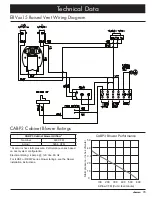
Vertical
non-combustible
surface rear wall
Notches for self-rimming
style installations, see range
installation instructions
Notches required for some raised vent
installations, see range
installation instructions
Backsplash
Countertop
overhang
See the range installation
instructions for exact countertop
and cabinet dimensions
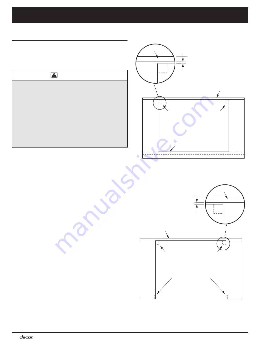
Vertical
non-combustible
surface rear wall
Notches required for some rasied vent
installations, see cooktop
installation instructions
Backsplash
Countertop
overhang
See the cooktop installation
instructions for exact countertop
and cabinet dimensions
Flush with back side
of cabinet front
Range Cabinet/Countertop Cutout - Top View
Cooktop Cabinet/Countertop Cutout - Top View
Summary of Contents for ERV3015
Page 18: ...16 Notes ...
Page 19: ...17 ...


