20
English
Installation Instructions
Preparing for Installation
•
If the gas or electric service provided does not meet the product specifications, discontinue installation,
and call the dealer, gas supplier, or a licensed electrician.
•
Before moving the range into place, install the anti-tip bracket (see below for instructions).
Unpacking the Range
Unpack the parts box, and verify that all specified components are present (see Pg. 9 or 10). If any item is miss
-
ing or damaged, contact your dealer immediately. Do not install a damaged or incomplete range.
Installing a Backguard (optional)
Install the backguard before making the range gas and electrical connections. Install according to the back-
guard kit instructions.
Approved Backguard Models
Backguard Description For Range Model
A
H
B30D
6
6
” tall for model HDPRS30, HDERS30
A
H
B30D9
9” tall for model HDPRS30, HDERS30
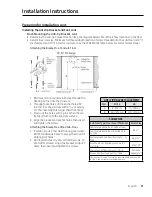
Installing the Anti-tip Bracket and Foot
There are two ways to mount the anti-tip bracket: Floor mounting (preferred), and wall mounting (Pg. 19).
Wall-mount the bracket if floor mounting is unsuitable; however, if the range’s front panel is over 26 1/2” (67.3
cm) from the back wall or if the floor is too thick, floor mounting must be used.
Floor-Mounting the Anti-tip Bracket
To perform as designed, the anti-tip bracket must attach to the concrete slab or wood sub-floor below any
upper flooring (including cement board). Do not attach the anti-tip bracket directly to floor coverings such
as ceramic/asphalt tile or linoleum.
•
Four plastic anchors are provided with three sizes (4 each)
of #8 and #12 Phillips head screws for attaching the anti-tip
bracket to the floor. Use both anchors and four of the screws
to attach the bracket to a concrete sub-floor. Do not use
anchors on a wood sub-floor.
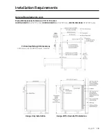
• Determine the location of the range center line and front
panel for the range’s final position (see
Product Dimen-
sions
, Pg. 13) and the actual cabinet/cutout dimensions
used for the installation.

