background image

2


WARNING

• 

IMPORTANT:

 Observe all governing codes and ordinances 

during planning and installation. Contact your local building 

department for further information.

•  To prevent an electric shock hazard, the power supply 

must meet the specifications stated below. It is the owner’s 

responsibility to make sure that the electrical service meets 

electrical requirements and that the electrical outlet has 

been properly installed by a licensed electrician.

The appliance installation must be electrically grounded in 

accordance with local codes or, in the absence of local codes, 

with the National Electrical Code, ANSI/ NFPA 70:

Electrical Requirements

•  The range is supplied with a factory installed, 6 foot long, power 

cord with a three-prong grounding plug. It is connected to the 

chassis at the rear of the range. It must be connected to a 

dedicated, grounded three-prong electrical outlet.

•  The correct voltage, frequency and amperage must be supplied 

to the appliance from a separate, grounded, circuit that is 

protected by a properly sized circuit breaker or time delay fuse.

Model

Circuit Required

Total Connected Load*

HGPR36S

120 Vac, 60 Hz, 15 Amp.

120 Vac 60 Hz, 

5.0 Amp.

HGPR48S

120 Vac, 60 Hz, 15 Amp.

120 Vac 60 Hz, 

8.0 Amp.

*These specifications for reference only. Refer to the rating label for exact specifications 

(see below for location).

Planning the Installation

Gas-Supply Requirements

•  Installation of this range must conform to local codes or, in their 

absence, to the National Fuel Gas Code, ANSI Z223.1/NFPA 54.

•  The range being installed must match the home gas service 

(natural or LP gas).

•  If using the range above 4000 ft. (1219 m) altitude, ensure it is 

equipped for high-altitude use. See the rating label and graphic 

on the inside front cover to verify the correct model.

•  This table has gas-supply pressure requirements:

GAS-SUPPLY PRESSURE REQUIREMENTS*

Gas Type

Min. Manifold Pressure Minimum Gas-Supply 

Pressure**

Natural Gas

5” Water Column

6” Water Column

Liquid Propane (LP)

10” Water Column

11” Water Column

*The gas supply pressure for testing the regulator setting shall be at least 1 inch 

water column (249 Pa) above the specified manifold pressure’ **maximum gas supply 

pressure for all models: 1/2 psi.
The ratings above are for reference only. See the rating label for exact specifications.

•  Use only the factory-installed regulator. The regulator inlet 

receives a 3/4” gas line. The range ships with a 1/2”-to-3/4” 

adapter connected to the regulator.

B

A

Power 

cord

Gas 

Inlet

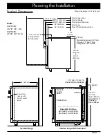
GAS-/ELECTRICAL-ACCESS DIMENSIONS

Model

A

B

HGPR36S

13 1/16” to 14 3/8” (33.2  to 36.5 cm)

7 5/16”  (18.6 cm)

HGPR48S

13 1/16” to 14 3/8” (33.2  to 36.5 cm)

4 1/4”  (10.8 cm)

Rating 

Label

Summary of Contents for HGPR36S

Page 1: ...Installation Instructions Heritage Gas Range HGPR36S HGPR48S Part No 108531 Rev A...

Page 2: ...n 8 Reinstalling the Oven Door 8 Installing the Burner Knobs 9 Assembling the Cooktop 10 Verifying Proper Function 11 Moving the Range for Service 11 Installation Checklist 11 Customer Service Informa...

Page 3: ...diatement votre fournisseur de gaz de la maison d un voisin et suivez les instructions du fournisseur Si vous ne pouvez pas joindre votre fournisseur de gaz appelez le service d incendie L installati...

Page 4: ...ese specifications for reference only Refer to the rating label for exact specifications see below for location Planning the Installation Gas Supply Requirements Installation of this range must confor...

Page 5: ...s are available 3 7 62 cm 24 61 0 cm Cabinet face lines up with back of control panel Product tolerances 1 16 1 6 mm Product Dimensions Width HGPR36S 35 7 8 91 1 cm HGPR48S 47 7 8 121 6 cm Installed R...

Page 6: ...unless otherwise stated Range Downdraft Vent HGPR36S ERV36 ER HGPR48S ERV48 ER Range 1 5 Low Profile Backguard HGPR36S APB36GLP HGPR48S APB48GLP Cabinet Layout All maximum minimum dimensions and clea...

Page 7: ...3 Grates 8 Standard burner caps 4 brass 4 porcelain 4 Standard burner rings 4 SimmerSear burner caps 2 brass 2 porcelain 2 SimmerSear burner rings 2 SimmerSear burner heads 2 GlideRack oven racks 1 S...

Page 8: ...n the base of the bracket and thread them into the anchors Ensure the screw threads engage the anchor 6 Tighten the screws Attaching the Bracket To a Wooden Sub Floor 1 If there is a hard floor coveri...

Page 9: ...onnect the range and shut off valve from the gas supply piping for pressure tests over 1 2 psi 3 5 kPa The shut off valve must be closed during pressure testing at or below 1 2 psi 3 5 kPa Check all g...

Page 10: ...perty damage Before opening the door ensure the notch on the bottom of each hinge rests on the lower lip of each hinge receptacle Flip the hinge locks toward the range immediately after installing the...

Page 11: ...ing NOTE A D shaped key on the back of each knob mates with the D shaped valve stem to ensure proper installation and function The range has three types of burner control knobs Installation Instructio...

Page 12: ...heir corresponding dimples formed into the spill tray Standard Burner Installation STEP 1 Put burner ring on top of head STEP 2 Turn ring until it drops into place STEP 3 Install burner caps Ridge on...

Page 13: ...heat 10 Turn off the oven 11 Model HGPR48S Verify the proper function of both ovens If the range does not operate properly 1 Check the electrical connections and gas supply to ensure that the install...

Page 14: ...Notes Notes...

Page 15: ...Notes...

Page 16: ...Dacor 14425 Clark Avenue City of Industry CA 91745 Phone 800 793 0093 Fax 626 403 3130 www dacor com...

Reviews: