background image

E5

Design Specifications

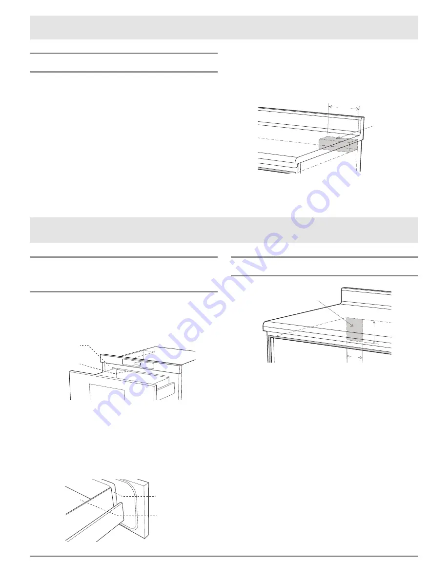
ANTI-TIP BLOCK

NORMAL INSTALLATION STEPS

ANTI-TIP BLOCK INSTALLATION INSTRUCTIONS

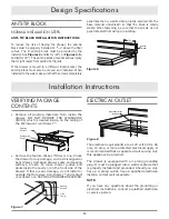
To reduce the risk of tipping the drawer, the anti-tip 

block must be properly installed 14 

13

/

16

" above the floor 

cutout. The 6" anti-tip block must be provided by the 

installer. See Figures 2 and 6 for (24") or Figures 4, 5, 

and (for 30"). The anti-tip block prevents serious injury 

that might result from spilled hot liquids.

If the drawer is moved to a different location later, the 

anti-tip block must also be moved and installed. When 

installed to the wall, make sure that the screws completely 

VERIFYING PACKAGE 

CONTENTS

• Remove all packing materials from inside the

drawer. DO NOT REMOVE THE WAVEGUIDE

COVER, which is located inside, on the ceiling of

the Microwave In-A-Drawer™.

Waveguide 

Cover

Sealing 

Surface

• Remove the feature sticker, if there is one. Check

the drawer for any damage, such as misaligned or

bent drawer, damaged drawer seals and sealing

surfaces, broken or loose drawer guides and

dents inside the cavity or on the front side of the

drawer. If there is any damage, do not install or

operate the Microwave In-A-Drawer™ and contact

your dealer or a DACOR AUTHORIZED SERVICER.

Sealing 

Surface

Oven 

Cavity

Figure 7 

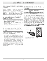
ELECTRICAL OUTLET

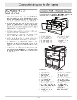
4"

5"

electrical outlet

location

anti-tip

block

(6")

Figure 8 

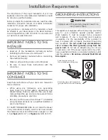
The electrical requirements are a 120 volt 60 Hz, AC 

only, 15 amp. or more protected electrical supply. It 

is recommended that a separate circuit serving only 

this appliance be provided.

The drawer is equipped with a 3-prong grounding 

plug. It must be plugged into a wall receptacle that 

is properly installed and grounded. Should you only 

have a 2-prong outlet, have a qualified electrician 

install a correct wall receptacle.

NOTE: 

If you have any questions about the grounding or 

electrical instructions, consult a qualified electrician 

or service person.

penetrate the dry wall and are properly secured into the 

base material underneath so that the block is totally 

stable. When fastening, be sure that the screws do not 

penetrate electrical wiring or plumbing.

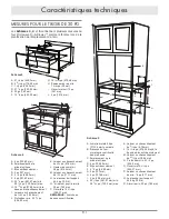
4"

5"

electrical outlet

location

anti-tip

block

(6")

Figure 6

Installation Instructions

Summary of Contents for Modernist Microwave In-A-Drawer DMR30M977WS

Page 1: ...Specifications 3 5 Clearances and Dimensions 3 24 Drawer Measurements 3 30 Drawer Measurements 4 Anti tip Block 5 Installation Instructions 5 6 Verifying Package Contents 5 Electrical Outlet 5 Drawer...
Page 2: ...OW ABOUT SAFETY INSTRUCTIONS Warnings and Important Safety Instructions appearing in this guide are not meant to cover all possible conditions and situations that may occur Always use common sense cau...

Page 3: ...use and care manual and follow all safety precautions carefully Be sure your Microwave In A Drawer is installed and grounded properly by a qualified installer or service technician For SAFETY CONSIDE...

Page 4: ...oven Be sure that the clearance of the floor between the wall oven and the drawer is a minimum of 2 The Microwave In A Drawer interior will easily accommodate a 9 x 13 oblong dish or bag of microwave...

Page 5: ...minimum overlap L 36 nominal countertop height M Allow 1 8 minimum overlap N Floor must support 100 lbs O 30 cabinet minimum P 15 9 16 opening NOTE Open Top Cabinet illustrated Figure 5 A 84 nominal...

Page 6: ...s broken or loose drawer guides and dents inside the cavity or on the front side of the drawer If there is any damage do not install or operate the Microwave In A Drawer and contact your dealer or a D...

Page 7: ...ddress Please call or write if you have inquiries about your microwave product and or need to order parts 4 Screws Parts Supplied Figure 9B DRAWER INSTALLATION Figure 9A 1 Place the drawer adjacent to...

Page 8: ...hniques 10 11 D gagements et dimensions 10 Mesures pour le tiroir de 24 po 10 Mesures pour le tiroir de 30 po 11 Bloc anti basculement 12 Directives d installation 12 13 V rification du contenu de l e...

Page 9: ...DE S CURIT Les mises en garde et les importantes consignes de s curit apparaissant dans ce manuel ne couvrent pas toutes les conditions et situations possibles Il faut exercer son bon sens de la prude...

Page 10: ...totalit des directives d installation Il contient des renseignements n cessaires pour un bon la s curit de l installation Il faut acheminer les questions ou les probl mes concernant l installation vot...

Page 11: ...s pla t voir les instructions pour le montage encastr inclus avec le affleurant vent de d flecteur A 6 po 152 40 mm B Emplacement de la prise lectrique C Bloc antibasculement D 5 po 127 mm E 3 1 2 po...

Page 12: ...5 A Armoire murale 84 po 2133 6 mm nominale B D coupe du four mural optionnel illustr dans le dessin C Emplacement de la prise lectrique D 6 po 152 40 mm E Bloc anti basculement F 3 1 2 po 88 90 mm G...

Page 13: ...si res du tiroir ne sont pas bris es ou desserr es et que l int rieur de la cavit ou la fa ade ne porte aucune trace de coups En cas de quelque dommage que ce soit ne pas faire fonctionner le four mic...

Page 14: ...entretien Veuillez appeler ou crire si vous avez des questions au sujet de votre four micro ondes ou si vous avez besoin de commander des pi ces INSTALLATION DU TIROIR Sch ma 9A 1 Placer le four pr s...

Page 15: ...Appliances Inc Neither this book nor any information or images contained herein may be copied or used in whole or in part without the express written permission of Distinctive Appliances Inc L informa...

Reviews: