


i
nsTallaTion
s
peCifiCaTions
NOTES:
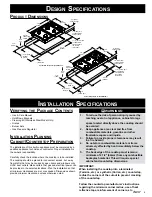
1. If cabinet storage space is to be provided directly
above the cooktop, the risk of personal injury
may be reduced by installing a ventilating hood
that projects horizontally a minimum of 5 inches
beyond the face of the cabinets.
2. Allow a minimum 1/4 inch clearance between
the bottom of the cooktop chassis and all
combustible surfaces, including the upper edge of
a drawer installed below the cooktop.
3. Access to the underside of the cooktop and the
junction box must be provided for inspection and
service.
4. A fixed shelf should not be installed below the
cooktop.
5. Clearance inside the cabinet must allow for proper
side mounting bracket installation.
6. All models are designed for 24” (610mm)
minimum base cabinet depth.
7. The maximum depth of cabinets installed above
cooktop is 13 inches (330mm).
Plan the installation so that the electrical connection, gas shut-off
valve, and pressure regulator are accessible from the front of the
cabinet.
Model
“A”
Minimum
“A”
Recommended
PGM304-1 30” (762mm)
36” (914mm)
PGM365-1 36” (914mm)
42” (1067mm)
Model
“B”
Minimum
PGM304-1
29” (737mm)
PGM365-1
35 1/4” (895mm)
13"
(330mm)
Maximum
A
3 1/8"
(79mm)
18"
(457mm)
Minimum
30"
(762mm)
Minimum
Clearances to Combustibles
1/4” (6mm)
Mimimum clearance
to combustible
surfaces
B
Under Cabinet Clearances
g
as
and
e
leCTRiCal
s
upply
R
equiRemenTs
The PGM cooktops are supplied with a factory installed three-
prong, grounding plug.
It is the owner's responsibility to ensure that the electrical
connection of this appliance is performed by a qualified
electrician. The electrical installation, including minimum supply
wire size and grounding, must be done in accordance with
National Electric Code ANSI/ NFPA 70* and local codes and
ordinances.
*A copy of this standard may be obtained from:
National Fire Protection Association
1 Batterymarch Park
Quincy, MA 02269-9101
NOTES:
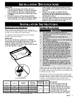
1. All gas cooktops have the utilities located in the
back right corner as you face the front of the
appliance.
2. Each cooktop ships with a factory regulator in the
box.
Check your local building codes for the proper method of
installation. In the absence of local codes, this appliance should
be installed in accordance with the National Fuel Gas Code ANSI
Z223.1/NFPA 54. Be certain that the appliance being installed is
correct for the gas service being provided. Refer to the data plate
located on the side of the cooktop chassis.
The correct voltage, frequency and amperage must be supplied to
the appliance from an isolated, grounded circuit which is protected
by a properly sized circuit breaker or time-delay fuse.
The cooktop must be connected to the power supply with copper
wire only. The use of aluminum wire may result in unsatisfactory
connections. Flexible armored or non-metallic, sheathed copper
cable (with a grounding wire) should be used to supply electrical
power to the junction box or receptacle.
The cooktop’s factory-equipped, three-prong grounding plug must
be inserted into a mating grounding-type receptacle in accordance
with National Electric Code and applicable state, municipal and
local codes.
Be certain to locate the junction box or electrical outlet so the
electrical supply may be easily disconnected in the event that
service becomes necessary. Also, provide extra slack in the cable
to allow the cooktop to be removed for servicing.
g
as
s
upply
R
equiRemenTs
e
leCTRiCal
R
equiRemenTs
g
as
and
e
leCTRiCal
s
upply
R
equiRemenTs
Summary of Contents for Preference PGM304-1
Page 2: ......
Page 10: ...NOTES...
Page 11: ...NOTES...
Page 12: ...10 NOTES...
Page 13: ...11 NOTES...
Page 14: ...12 NOTES...
Page 15: ...13 NOTES...


