


i
nsTallaTion
i
nsTRuCTions
i
nsTalling
b
uRneR
C
omponenTs
Before beginning the test procedure, ensure that the gas supply
is turned off at the shut-off valve, all cooktop control valves are in
the “OFF” position, and all burner heads, burner caps, and grates
are properly positioned on the cooktop.
Depress and rotate one knob at a time counterclockwise to the
“HIGH” position. Verify that associated burner igniter sparks, then
return the knob to the “OFF” position. Repeat for all knobs.
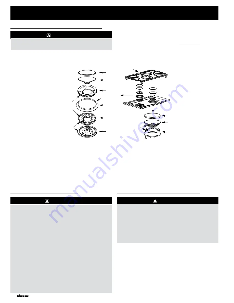
IMPORTANT:
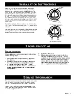
When installing the burner components, twist each
piece back and forth until it drops completely
into
place. The burners will not operate properly unless
all of the burner pieces are properly seated.
Burner Components
Remove the burner covers, brass burner heads, burner caps,
and porcelain grates from their shipping packages. Assemble
the burners as shown in the diagram. Make sure each piece is
properly seated. Place each grate onto the cooktop. Be certain
that the rubber feet are positioned in the locating dimples.
e
leCTRiCal
C
onneCTion
1. Ensure that the power supply is disconnected
before proceeding.
2. Verify that the power supply matches the
ratings found on the appliance data plate before
proceeding.
3. The complete appliance must be properly
grounded at all times when electrical power is
applied.
4. Do not ground the appliance with the neutral
(white) house supply wire. A separate ground
wire must be utilized.
5. If aluminum house supply wiring is utilized,
splice the appliance copper wires to the
aluminum house wiring using special connectors
designed and agency-certified for joining copper
and aluminum.
Plug the three-prong plug from the appliance into the properly
grounded and polarized wall receptacle.
WARNINGS:
V
eRifying
p
RopeR
o
peRaTion
WARNING:
1. The cooktop and shut-off valve must be
disconnected from the gas supply piping during
any pressure testing exceeding 1/2 pound per
square inch (3.5 kPA).
2. The cooktop must be isolated from the gas
supply piping by closing the shut-off valve
during any pressure testing at or below 1/2
pound per square inch (3.5 kPA).
WARNING:
Never attempt to operate the cooktop with any of the
burner heads, burner caps, or grates removed.
Burner Cap
Burner Head
Base
Cross Ring
Skirt
Cap Cover
Wide Side
Down!
Insert Pin on Bottom
of Cross Ring into
Hole on Base
Put Hole in Bottom
of Burner Head Over Pin
on Top of Cross Ring
PGM Burner Components
Burner Head
Grate
Cap Cover
Line Up Notch
on Bottom of
Head with Igniter
Single Burner Assembly
Dual Burner Assembly
Base
Summary of Contents for Preference PGM304-1
Page 2: ......
Page 10: ...NOTES...
Page 11: ...NOTES...
Page 12: ...10 NOTES...
Page 13: ...11 NOTES...
Page 14: ...12 NOTES...
Page 15: ...13 NOTES...


